This audio amplifier circuit diagram is based on the STA550 fully integrated power module designed to implement a BASH® amplifier when used in conjunction with STABP01 digital processor.
The STA550 audio amplifier is capable to provide a maximum output power of 70 watts on two channels ( 70 + 70 watts) .
The distortions of this power amplifier are 10 % at maximum power 70 +70 watts or 0.5% at 55 + 55 watts .
This power amplifier circuit require a multi voltage power supply , because the amplifier require : +Vs Positive supply voltage referred to pin 13 (GND), Negative supply voltage referred to pin 13 (GND) -Vs, VCD+
Positive supply voltage tracking rail, VCD- Negative supply voltage tracking rail .
The +Vs Positive supply voltage can be : +20 to +30 volts, -Vs Negative supply voltage : -10 to -22 volts , Positive supply voltage tracking rail VCD+ : +3 to 17 volts , Negative supply voltage tracking rail VCD- : -17 to -3 volts .
VCD- must not be more negative than -Vs and VCD+ must not be more positive than +VS .
As you can see in the circuit diagram , this audio amplifier provide a stand by and muting function .
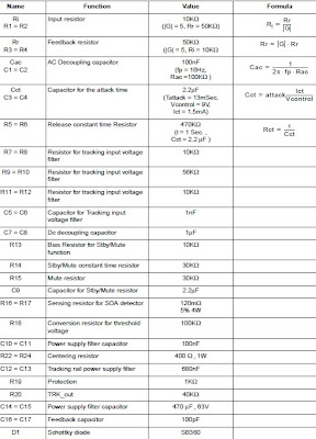
In this circuit diagram, R1/R3 (or R2/R4) ratio fix the gain of the preamplifier.
If the input signal is very low, is possible to increase the gain fixing the product Vin*G = cost.
In that case is possible to increase G decreasing R1,2 from 10KW until 2KW without relevant effetcs on the circuit behavior and remaining in the operating range Iin_max = Vin_max/R1(2),<1mA.
So it is possible to increase the preamplifier gain until 25.
In the suggested application circuit the supply voltage to obtain 75W (Power Output) on 8W (Rload) is:
Vsupply = DV + IL, MAX × RDSon
As you can see in the showed circuit diagram ,the STA550 audio amplifier require few external components ( most of them are resistors and capacitors ) and is very easy to design . If you want to modify this circuit diagram please consult the manufacturer datasheet .
S: electroniq.net/audio/sta550-70-70-watts-audio-amplifier.html


