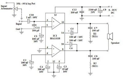
This audio amplifier circuit diagram is a class AB audio power amplifier based on the Hitachi HA13118 audio integrated circuit . The Hitachi HA13118 audio amplifier circuit provide a high power output from a low voltage supply using the bridge tied load method, and a high gain of 55dB. This audio amplifier is ideal for audio applications where the input signal has a very low level .
The Hitachi HA13118 audio amplifier circuit can provide a maximum 18W power in a 4 ohms load using 18 volts DC power Supply but also can be obtained various output power : > 5W RMS on 8 ohm load using 18V DC supply , > 6W RMS on 4 ohm load using 12V DC supply .
Other specifications for this amplifier are :
S/N ratio : > 70 dB , THD < 0.2% @ 1W , Freq. Response : ~ 30 Hz to 30 kHz, input level : < 25 mV , input Impedance ~ 30 k ohm .
For the Hitachi HA13118 audio amplifier circuit you will need a power supply that will provide a DC voltage between 8 and 18Vand at least 1 to 2 Amps.
If you want to obtain the maximum output power you will need a power supply that will provide 18 volts DC at more than 2 A , and if you will use a 4 ohms speaker .
The construction of this power supply is very simple and is require few external components .
Be careful when soldering the IC not to use excessive heat. If it’s possible use some heat sink compound between the heat sink & the IC .
If you need volume control or to attenuate the input signal you can connect a logarithmic potentiometer at the input pin .


