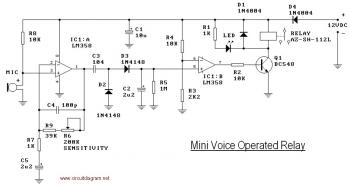
This is the circuit diagram of a voice operated relay. It similar with sound activation switch circuit which will turn on and turn off (connect and disconnect) the switch depending on the sound input. The output switch of this circuit is act by a relay.
Component Parts list:
R1, R7 1K R2, R4, R8 10K R3 2K2 R5 1M R6 200K R9 39K D1, D4 1N4004 D2, D3 1N4148 C2, C5 2.2uF/16V mini ecap | C1 10uF/16V mini ecap C4 100pF C3 100nF Q1 BC548 IC1 LM358 (of Hitachi HA17358) 8 pin IC socket Relay AX-SH-112L LED 3mm Electret microphone |
This mini-VOX – voice operated relay – is based on a circuit published in Silicon Chip, 9/1994, p31.
The off delay time may be adjusted by varying R3 and R4. Reducing R3 will result in a longer release time.
You could change the release time constant (C2 & R5) to say 30 seconds and use the VOX as a light switch with this delay time before turning off. Increase C2 to say 10uF and R3 to 3M3.
To make the easy adjustment, you may use potensiometer or trimpot to varying the value of resistor. You will need additional place on the PCB but it will easier for you to make some adjustment
The kit of this circuit available at kitsrus.com anf electronickits.com, you may buy the circuit there.
HERE the manual instruction of this Mini Voice Operated Relay circuit
circuitdiagram.net/mini-voice-operated-relay.html


