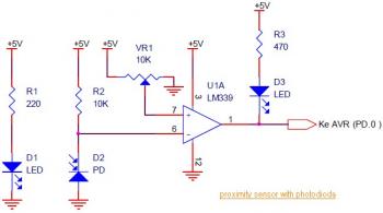
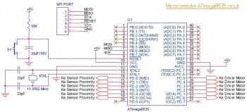
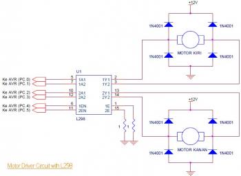
This is the circuit diagram of Line Follower / Line Tracker robot. The circuit taken from the tutorial documentation. You may download the full tutorial at the end of this article.
The line follower robot use 8 pieces of proximity sensor module. The sensor module use photodioda for detecting the reclection of light from the line/floor.
Proximity / Line Detector circuit:
ATmega8535 is a cheap and great microcontroller for your robot. This microcontroller is very easy to use, very easy to find, very easy to program.
Microcontroller ATmega8535 circuit:
The motor driver L298 able to control the motor with current output up to 2A for single DC motor. For double DC motors, there should be up to 1A for each output channel. This motor driver is very good for small and medium DC motor. L298 is great motor driver for small and medium size or robot such as line follower robot and fire fighter robot.
Motor Driver circuit with L298:
Download the complete line follower robot turotial which containing od schematic diagram, robot design and source code in PDF version (Indonesian language):
Download Link


