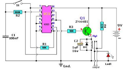
A very simple alternating on off switch electronic circuit project can be designed using an 4096 CMOS hex inverter and some common electronic parts.
IC1is a regular Hex-inverter type and is constructed with MOS P-channel and N-channel enhancement mode devices in a single monolithic structure.
First push from this alternating on off switch activates the relay and another push de-activates the relay.
The type for D1 in not critical, even a 1N4148 will work.
Q1 transistor is an 2N4401 type , but can be replaced with some other type like : N100, NTE123A, 2N3904, 2N2222, 2N4013, etc.
For C2, if you find the relay acts not fast enough, you can change it to a lower value or use a ceramic cap of around 0.1μF.
The circuit can be powered from a 9 or 12 volts DC power supply circuit .
Unused input pins must be connected to an appropriate logic level and unused output pins must be left open.
Relay used in this project is an 6 volts relay type . R4 and LED1 are optional and can be removed from the circuit .


