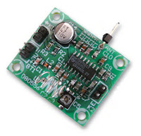
This is a nearly complete integrated receiver circuit which has been specifically designed for portable radios and the like, requiring only a minimum of external components. As a result the final dimensions of the radio can be kept very small. The IC uses a frequency-locked-loop (FLL) system with an intermediate frequency of 76 kHz. The selectivity is obtained with the aid of active RC filters. The only ‘calibration’ adjustment in the circuit is the resonance frequency of the oscillator for the tuning.
The RF signal enters at pin 12 and is amplified first, after which it is transformed down by the mixer and passes through two IF filters. It is subsequently limited in amplitude. The IF limiter also supplies a signal for the optional signal strength indicator (via pin 9). The limited FM signal then goes to the demodulator and the correlator which decides whether the signal is tuned in properly. The demodulated are entirely available. This is also the reason that it is not recommended to connect the audio output directly to the line input of an audio system.
FM Receiver Circuit Schematic
The complete circuit for the FM receiver is shown above. The design is virtually identical to the test circuit shown in the datasheet for the IC, because this is difficult to improve even a little without adding a lot of additional electronics. Now we only need a few resistors and capacitors plus a coil. The tuning circuit
correctly covers the entire VHF FM broadcast band from 88 to 108 MHz. Tuning is done with trimmer capacitor C5.
There is also a connection (K2) for a simple signal strength meter. Via resistor R1 and decoupling capacitor C9, pin 9 supplies a DC voltage which is a measure of the received signal strength. At 170 μA the output current is too small to drive an LED, but you could connect an ‘oldfashioned’ moving coil meter. For the antenna you can use a simple wire antenna of about 75 cm long, which is soldered directly to the PCB.
FM Receiver Printed Circuit Board
SMD parts are used everywhere to keep the dimensions as small as possible. Soldering these small parts requires a bit of practice however. The dimensions of this tiny PCB are only 3.2 × 2.7 cm! The circuit contains no difficult coils, only the VCO requires an air-cored inductor with only 4 turns.
This receiver is a mono implementation, but at the output (as already mentioned) the entire multiplexed signal (up to 53 kHz) is available. By using a PLL stereo decoder, such as the TDA7040T, a stereo signal can be generated in a traightforward way from the output signal of the TDA7021T.
FM Receiver Circuit Parts List
Resistors (SMD 0805)
R1 = 8kΩ2
R2 = 10kΩ
R3 = 390Ω
Capacitors (SMD 0805)
C1,C3 = 10nF
C2,C6,C9,C16 = 100nF
C4 = 33pF
C5 = 25pF trimmer (Murata type TZB4Z250AB10R00)
C7,C10 = 1nF5
C8 = 820pF
C11 = 1nF
C12 = 68pF
C13 = 220pF
C14 = 47μF 10V (Nichicon UWX1A470MCL1GB 5.5mmL chip type)
C15 = 3nF3
Inductors
L1 = 36nH (4 turns 0.5mm silver-plated wire, inside diameter 4mm; length 7mm)
L2 = 1μH, SMD case 0805 (fres > 300 MHz)
Semiconductors
IC1 = TDA7021T (SMD in SO16 case)
Miscellaneous
K1,K2 = 2-way pinheader
BT1 = 2-way pinheader + battery holder for 2-4 AA batteries


