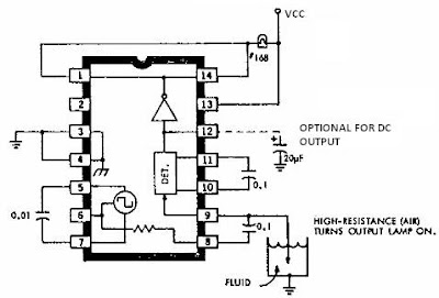

This electronic liquid detector circuit diagram is based on the ULN2429A monolithic bipolar integrated circuit designed for detecting the absence or presence of many different types of liquids . The ULN2429 electronic liquid detector circuit can be used in automotive , home or industrial applications .
The absence or presence of the liquid is determined by comparing the loaded probe resistance (probe immersed in the fluid ) with an internal or external resistance . At the output you can connect a LED , incandescence lamp , loud speaker or even such relays or solenoids, but just I you connect at pin 12 a capacitor , to provide a dc output ( typically the output signal is a square wave ) .
If you need to connect at the output a device that need more than 30 volts you can use the ULN2429A-1 which is identical , but support devices with operation up to 50 volts .
Main features of the ULN2429A are : high output current , AC or DC output , single wire probe , low external parts require , reverse voltage protection , internal voltage regulation .
This fluid detector electronic circuit need to be powered using a power supply that provide an output voltage between 10 and 16 volts .


