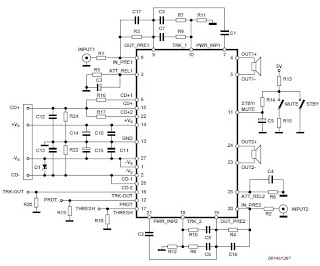
This power audio amplifier electronic project is based on the STA575 fully integrated power module designed to implement a BASH® amplifier when used in conjunction with STABP01 digital processor.
This power audio amplifier electronic project is based on the STA575 is capable to provide a maximum 100 watts output continuous power per channel ( on two channels ) on a 4 or 8 ohms load .
The circuit contains all the blocks to build a stereo amplifier. Each single channel is based on the Output Bridge Power Amplifier, and its protection circuit.
STA575 power audio amplifier can be set in three states by the Stby/mute pin: Standby ( Vpin < 0.8V), Mute (1.6V < Vpin < 2.5V), and Play (Vpin > 4V).
In the Standby mode all the circuits involved in the signal path are in off condition, instead in Mute mode the circuits are biased but the Speakers Outputs are forced to ground potential.
These voltages can be get by the external RC network connected to Stby/Mute pin.
The same block is used to force quickly the I.C. In standby mode or in mute mode when the I.C. dangerous condition has been detected.
The protection of STA575 power audio amplifier are implemented by the Over Temperature, Unbalance .
The Output bridge amplifier makes the single-ended to Differential conversion of the Audio signal using two power amplifiers, one in non-inverting configuration with gain equal to 2 and the other in inverting configuration with unity gain.
To protect the output transistors of the power bridge a power detector is implemented .
To power this 200 watt stereo power audio amplifier you’ll need a DC power source that will provide the following output voltages : Vs+ = 28V, Vs- = -23V, VCD+ = 20V, VCD- = -20V and you’ll need a 8 ohms load .
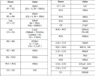
In the table bellow you can see values for electronic parts required by this 200 watt stereo power audio amplifier electronic project .


