A low-cost circuit of an FM booster that can be used to listen programs from distant FM stations clearly. The circuit comprises a common-emitter tuned RF preamplifier wired around VHF/UHF transistor 2SC2570 ( C2570).
This FM booster circuit is constructed using few common components ( not require some special components ) and provide a very good gain .
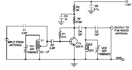
To calibrate this circuit you need to adjust input/output trimmers (VC1/VC2) for maximum gain.
Input coil L1 consists of four turns of 20SWG enamelled copper wire (slightly space wound) over 5mm diameter former.
It is tapped at the first turn from ground lead side. Coil L2 is similar to L1, but has only three turns.
Both of the trimmers are 22pF value .This FM radio signal booster needs to be powered by a 12 volts DC power supply
.
more at: electroniq.net/radio-frequency/fm-booster-schematic-circuit.html


