Description:
A novel supply voltage monitor which uses a LED to show the status of a power supply.

Notes:
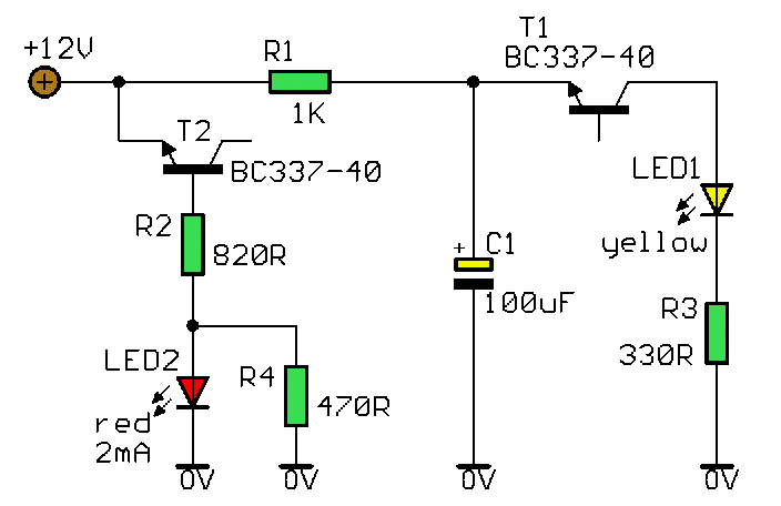
This simple and slightly odd circuit can clearly show the level of the supply voltage (in a larger device): as long as the indicator has good 12 volts at its input, LED1 gives steady, uninterrupted (for the naked eye) yellow light. If the input voltage falls below 11 V, LED1 will start to blink and the blinking will just get slower and slower if the voltage drops further - giving very clear and intuitive representation of the supply's status. The blinking will stop and LED1 will finally go out at a little below 9 volts.
On the other hand, if the input voltage rises to 13 V, LED2 will start to glow, getting at almost full power at 14 V.
The characteristic voltages can be adjusted primarily by adjusting the values of R1 and R4.
The base-emitter diode of T2 basically just stands in for a zener diode. The emitter-collector path of T1 is inversely polarized and if the input voltage is high enough - T1 will cause oscillations and the frequency will be proportional to the input voltage. The relaxation oscillator ceases cycling when the input voltage gets so low that it no longer can cause breakdown along the emitter-collector path.
Not all small NPN transistors show this kind of behavior when inversely polarized in a similar manner, but many do. BC337-40 can start oscillations at a relatively low voltage, other types generally require a volt or two more. If experimenting, be careful not to punch a hole through the device under test: they oscillate at 9-12 V or not at all.
Source:www.zen22142.zen.co.uk


