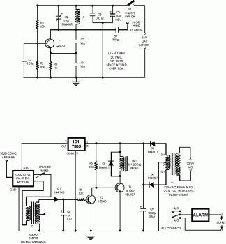
This circuit is a wireless car alarm system that is built using two circuit modules, namely modules of transmitter and receiver modules. This circuit works on FM radio waves. Car alarms can be used on vehicles that have a 6-12VDC power supply. You can use the voltage stabilizer if your car power supply is too large (eg 24V).
How the circuit works:
The mini VHF, FM transmitter is fitted in the vehicle at night when the car is parked in the car porch. The receiver unit is built with CXA1019. CXA1019 a single IC-based FM radio module which is freely available in the market, is kept inside.
Receiver is tuned to the transmitter’s frequency. When the transmitter is on and the signals are being received by FM radio receiver, no hissing noise is available at the output of receiver. Thus transistor T2 (BC548) does not conduct. This results in the relay driver transistor T3 getting its forward base bias via 10k resistor R5 and the relay gets energised.
When an intruder tries to drive the car and takes it a few metres away from the car porch, the radio link between the car (transmitter) and alarm (receiver) is broken. As a result FM radio module will generate hissing noise. Hissing AC signals are coupled to relay switching circuit via audio transformer. These AC signals are rectified and filtered by diode D1 and capacitor C8, and the resulting positive DC voltage provides a forward bias to transistor T2. Thus transistor T2 conducts, and it pulls the base of relay driver transistor T3 to ground level. The relay thus gets de-activated and the alarm connected via N/C contacts of relay is switched on.
If the intruder finds out about the wireless alarm (which already turned on) and disconnects the transmitter from battery, still remote alarm remains activated. It will not turn off the alarm because in the absence of signal, the receiver continues to produce hissing noise at its output. So the burglar alarm is fool-proof and highly reliable.
Circuit diagram source: www.electronic-circuits-diagrams.com


