Inverter from 9V to 13.5K with Circuit and Explanation


A transistor which supplies pulses of 150V inverter formed by a capacitor and a thyristor in series with the transformer 2, the periphery, the high voltage source is an inverter. The output pulse of 4.5kV to be applied to the network so as to achieve the output voltage of 13.5kV. (LN label) neon lamp is formed with a thyristor trigger pulse. 
Inverter from 9V to 13.5K with Circuit and Explanation


Transformer T1 has a relation 3000:500 Ω of the type used for audio output transistor. T2 is a secondary flash lamp trigger transformer 6kV. The inverter circuit requires a power supply 9VDC 0.01A current 


Warning: 
Application of this on the human body can cause serious physical injury that can cause to death. So don’t use in humans.
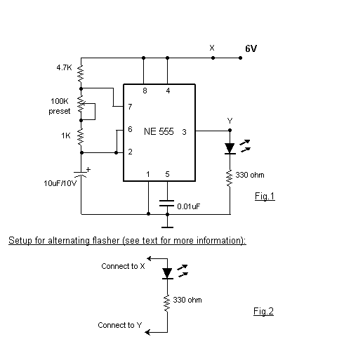
Blinking Light Circuit - Flasher Schematic simple


Blinking Light Circuit - Flasher Schematic simple 
Blinking Light Circuit - Flasher Schematic simple

How to increase The Regulator Output Voltage with Circuit and Explanation


In order to provide an output voltage higher than that provided by the regulator to provide a voltage regulator integrated circuit is often necessary accordingly. One way to achieve this is to connect the "common" to the midpoint of the voltage divider, and the IC regulator small quiescent current coming out from the common terminal to ground The problem with this method (~ 10 mA it is to have). 

Since the extent of this quiescent current is not strictly controlled, the total output voltage will be somewhat unpredictable. There is a possibility of help resistor divider low value, is a complication of inefficiency and heat dissipation.
How to increase The Regulator Output Voltage with Circuit and Explanation
increase The Regulator Output Voltage Circuit


24V from 12V regulator circuit diagram
The circuit presented here avoids the problem by using the transistor T1 to generate a low impedance at the regulator common terminal by emitter-follow action, while transferring the voltage divider from a relatively high-resistance divider network. The value of R3 is not critical but must be low enough to accept the highest quiescent current without causing T1 to turn-off.
If you want to report any meterial please