Latest new Inductor-Based Converter for Powering White LEDs in Series Connections Driving the LEDs can be in parallel and/or series connections. The


Driving the LEDs can be in parallel and/or series connections. The series method features inherent matching, but requires a higher supply voltage. For generating high voltages, an inductor-based converters are commonly used for this purpose.

The MAX8596Z switching regulator drives up to eight white LEDs in series

The MAX8596Z switching regulator is designed to drive up to eight white LEDs in series, as shown in the above picture. When choosing this type of converter, the output voltage rating of the Lx pin must be considered. An overvoltage lockout threshold of 32V to 36V protects the IC if an LED becomes open circuit.

The device has a 2.6V to 5.5V input voltage range allowing the IC to be powered from a single lithium battery or three NiCd/NiMH batteries.

Latest new Inductor-Based Converter for Powering White LEDs in Series Connections Driving the LEDs can be in parallel and/or series connections. The


Latest new Inductor-Based Converter for Powering White LEDs in Series Connections


Driving the LEDs can be in parallel and/or series connections. The series method features inherent matching, but requires a higher supply voltage. For generating high voltages, an inductor-based converters are commonly used for this purpose.

The MAX8596Z switching regulator drives up to eight white LEDs in series

The MAX8596Z switching regulator is designed to drive up to eight white LEDs in series, as shown in the above picture. When choosing this type of converter, the output voltage rating of the Lx pin must be considered. An overvoltage lockout threshold of 32V to 36V protects the IC if an LED becomes open circuit.

The device has a 2.6V to 5.5V input voltage range allowing the IC to be powered from a single lithium battery or three NiCd/NiMH batteries.

CA3140 Simple Differential input circuit and explanation


In some cases, we often encountered a differential input voltage required for measurement. Using only one operational amplifier, you can build an adapter to give your input for floating-ground reference voltage. In the circuit diagram is one example and you should try. Circuit diagram is very simple in using IC-OP Amp CA3140. Here is a schematic picture:

Differential input adapter

Use 1% tolerance metal film resistor for R1 and R2. Adjust VR1 to give zero output voltage when the input is shorted probe. You can use the supply voltage + UB-UB and between 3 to 20V, this is a symmetrical supply.

Differential Analog Circuit Switch circuit and explanation


This circuit is a differential analog circuit switches. The FM1208 monolithic dual differential multiplexer used in applications where the RDS (ON) must be the same match. Since RDS (ON) for monolithic dual tracks at better than 1% of the broad temperature range (-25 to 125 C) is making an unusual choice, but ideal for a multiplexer accurate. This greatly reduces the close tracking errors due to common mode signals. OP-Amp used are LM107. Here is a schematic drawing:


Source : National semiconductor Application

LM317 Voltage Regulator circuit and explanation


This is a Variable Voltage Regulator Circuit, which in this circuit is controlled by IC LM317T. Which is a LM317T adjustable 3 terminal positive voltage regulator capable of providing more than 1.5 amps through a variety of output volts 1,25-37. This device also has built in current and thermal shutdown limit which makes it essentially blow-out proof. This circuit can be used to create a stable power supply. On the working principles of circuit output voltage is set by two resistors R1 and R2 connected as shown below. Voltage through the R1 is a constant 1.25 volts and the adjustment terminal current is less than 100uA. Output voltage can be closely approximated from Vout = 1.25 * (1 + (R2/R1)) which ignores the adjustment terminal current but will be close if the current through R1 and R2 is several times larger. A minimum load of 10mA is required, so that the value of R1 can be selected down to 1.25 volts at 10mA or 120 ohms. Something less than 120 ohms can be used to ensure a minimum greater than 10mA current. Here is a picture of the circuit diagram:


In the picture above shows the LM317 used as 13.6 volt regulator. The 988 ohm resistor for R2 can be obtained with the standard 75 and 910 ohm in series. When the power is shut off to the regulator’s output voltage should fall faster than predicted. If not, a diode can be connected across the input / output terminals to protect against reverse voltage regulator. A 1uF tantalum or electrolytic capacitor 25uF entire output increase response and a small 0.1uF tantalum capacitor is recommended across the input if the regulator is located appreciable distance from power supply filter. Power transformer must be large enough so that the input voltage regulator will remain in the top 3 volts output at full load, or 16.6 volts to 13.6 volt output.

Resistor Calculator for LEDs (serial and parallel) V.2


Software that calculates the resistor value and its power consumption in different LED's circuit configurations (simple, series o parallel) according to the source voltage, the LED's voltage and the wanted current value. All are shown in the same screen in order to make direct comparisons on values.

How to calculate the value of a resistor using the color coded stripes on the resisto


To calculate the value of a resistor using the color coded stripes on the resistor, use the following procedure.


Step One: Turn the resistor so that the gold or silver stripe is at the right end of the resistor.

Step Two: Look at the color of the first two stripes on the left end. These correspond to the first two digits of the resistor value. Use the table given below to determine the first two digits.

Step Three: Look at the third stripe from the left. This corresponds to a multiplication value. Find the value using the table below.

Step Four: Multiply the two digit number from step two by the number from step three. This is the value of the resistor n ohms. The fourth stripe indicates the accuracy of the resistor. A gold stripe means the value of the resistor may vary by 5% from the value given by the stripes.

Resistor Color Codes (with gold or silver strip on right end)


Follow the above procedure with the examples below and soon you will be able to quickly determine the value of a resistor by just a glance at the color coded stripes.

Examples

Example1:
You are given a resistor whose stripes are colored from left to right as brown, black, orange, gold. Find the resistance value.

Step One: The gold stripe is on the right so go to Step Two.

Step Two: The first stripe is brown which has a value of 1. The second stripe is black which has a value of 0. Therefore the first two digits of the resistance value are 10.

Step Three: The third stripe is orange which means x 1,000.

Step Four: The value of the resistance is found as 10 x 1000 = 10,000 ohms (10 kilohms = 10 kohms).

The gold stripe means the actual value of the resistor mar vary by 5% meaning the actual value will be somewhere between 9,500 ohms and 10,500 ohms. (Since 5% of 10,000 = 0.05 x 10,000 = 500)


Example2:
You are given a resistor whose stripes are colored from left to right as orange, orange, brown, silver. Find the resistance value.

Step One: The silver stripe is on the right so go to Step Two.

Step Two: The first stripe is orange which has a value of 3. The second stripe is orange which has a value of 3. Therefore the first two digits of the resistance value are 33.

Step Three: The third stripe is brown which means x 10.

Step Four: The value of the resistance is found as 33 x 10 = 330 ohms.

The silver stripe means the actual value of the resistor mar vary by 10% meaning the actual value will be between 297 ohms and 363 ohms. (Since 10% of 330 = 0.10 x 330 = 33)


Example3:
You are given a resistor whose stripes are colored from left to right as blue, gray, red, gold. Find the resistance value.

Step One: The gold stripe is on the right so go to Step Two.

Step Two: The first stripe is blue which has a value of 6. The second stripe is gray which has a value of 8. Therefore the first two digits of the resistance value are 68.

Step Three: The third stripe is red which means x 100.

Step Four: The value of the resistance is found as 68 x 100 = 6800 ohms (6.8 kilohms = 6.8 kohms).

The gold stripe means the actual value of the resistor mar vary by 5% meaning the actual value will be somewhere between 6,460 ohms and 7,140 ohms. (Since 5% of 6,800 = 0.05 x 6,800 = 340)


Example 4:
You are given a resistor whose stripes are colored from left to right as green, brown, black, gold. Find the resistance value.

Step One: The gold stripe is on the right so go to Step Two.

Step Two: The first stripe is green which has a value of 5. The second stripe is brown which has a value of 1. Therefore the first two digits of the resistance value are 51.

Step Three: The third stripe is black which means x 1.

Step Four: The value of the resistance is found as 51 x 1 = 51 ohms.

The gold stripe means the actual value of the resistor mar vary by 5% meaning the actual value will be somewhere between 48.45 ohms and 53.55 ohms. (Since 5% of 51 = 0.05 x 51 = 2.55)


Other Resistor Information

There are some more rules that may be useful when working with resistors. You do not need to know them but if you need a resistor with a value that you do not have, you my be able to use the following information to create the value of resistor you need.

First Rule for Resistors : Series Connection

When two resistors are connected in series, as shown in Figure 1, the new resistance between points A and B is R1 + R2.

Figure 1


The resistors add together. For example if R1 = 500 ohms and R2 = 250 ohms then the resistance between points A and B would be R1 + R2 = 500 + 250 = 750 ohms.

Second Rule for Resistors : Parallel Connection

When two resistors are connected in parallel, as shown in Figure 2, the new resistance is smaller than either R1 or R2. The new resistance between points A and B is (R1 x R2) / (R1 + R2).

Figure 2


For example, if R1 = 500 and R2 = 250 then the resistance between points A and B = (500 x 250) / (500 + 250) = (125,000) / (750) = 167 ohms. If R1 = R2 then the new resistance is just R1 / 2.

Using these two rules, resistors can be combined to form new resistance values.

Bookmark and Share

How to Find Value of a Resistor by Color Codes


To calculate the value of a resistor using the color coded stripes on the resistor, use the following procedure.


Step One: Turn the resistor so that the gold or silver stripe is at the right end of the resistor.

Step Two: Look at the color of the first two stripes on the left end. These correspond to the first two digits of the resistor value. Use the table given below to determine the first two digits.

Step Three: Look at the third stripe from the left. This corresponds to a multiplication value. Find the value using the table below.

Step Four: Multiply the two digit number from step two by the number from step three. This is the value of the resistor n ohms. The fourth stripe indicates the accuracy of the resistor. A gold stripe means the value of the resistor may vary by 5% from the value given by the stripes.

Resistor Color Codes (with gold or silver strip on right end)


Follow the above procedure with the examples below and soon you will be able to quickly determine the value of a resistor by just a glance at the color coded stripes.

Examples

Example1:
You are given a resistor whose stripes are colored from left to right as brown, black, orange, gold. Find the resistance value.

Step One: The gold stripe is on the right so go to Step Two.

Step Two: The first stripe is brown which has a value of 1. The second stripe is black which has a value of 0. Therefore the first two digits of the resistance value are 10.

Step Three: The third stripe is orange which means x 1,000.

Step Four: The value of the resistance is found as 10 x 1000 = 10,000 ohms (10 kilohms = 10 kohms).

The gold stripe means the actual value of the resistor mar vary by 5% meaning the actual value will be somewhere between 9,500 ohms and 10,500 ohms. (Since 5% of 10,000 = 0.05 x 10,000 = 500)


Example2:
You are given a resistor whose stripes are colored from left to right as orange, orange, brown, silver. Find the resistance value.

Step One: The silver stripe is on the right so go to Step Two.

Step Two: The first stripe is orange which has a value of 3. The second stripe is orange which has a value of 3. Therefore the first two digits of the resistance value are 33.

Step Three: The third stripe is brown which means x 10.

Step Four: The value of the resistance is found as 33 x 10 = 330 ohms.

The silver stripe means the actual value of the resistor mar vary by 10% meaning the actual value will be between 297 ohms and 363 ohms. (Since 10% of 330 = 0.10 x 330 = 33)


Example3:
You are given a resistor whose stripes are colored from left to right as blue, gray, red, gold. Find the resistance value.

Step One: The gold stripe is on the right so go to Step Two.

Step Two: The first stripe is blue which has a value of 6. The second stripe is gray which has a value of 8. Therefore the first two digits of the resistance value are 68.

Step Three: The third stripe is red which means x 100.

Step Four: The value of the resistance is found as 68 x 100 = 6800 ohms (6.8 kilohms = 6.8 kohms).

The gold stripe means the actual value of the resistor mar vary by 5% meaning the actual value will be somewhere between 6,460 ohms and 7,140 ohms. (Since 5% of 6,800 = 0.05 x 6,800 = 340)


Example 4:
You are given a resistor whose stripes are colored from left to right as green, brown, black, gold. Find the resistance value.

Step One: The gold stripe is on the right so go to Step Two.

Step Two: The first stripe is green which has a value of 5. The second stripe is brown which has a value of 1. Therefore the first two digits of the resistance value are 51.

Step Three: The third stripe is black which means x 1.

Step Four: The value of the resistance is found as 51 x 1 = 51 ohms.

The gold stripe means the actual value of the resistor mar vary by 5% meaning the actual value will be somewhere between 48.45 ohms and 53.55 ohms. (Since 5% of 51 = 0.05 x 51 = 2.55)


Other Resistor Information

There are some more rules that may be useful when working with resistors. You do not need to know them but if you need a resistor with a value that you do not have, you my be able to use the following information to create the value of resistor you need.

First Rule for Resistors : Series Connection

When two resistors are connected in series, as shown in Figure 1, the new resistance between points A and B is R1 + R2.

Figure 1


The resistors add together. For example if R1 = 500 ohms and R2 = 250 ohms then the resistance between points A and B would be R1 + R2 = 500 + 250 = 750 ohms.

Second Rule for Resistors : Parallel Connection

When two resistors are connected in parallel, as shown in Figure 2, the new resistance is smaller than either R1 or R2. The new resistance between points A and B is (R1 x R2) / (R1 + R2).

Figure 2


For example, if R1 = 500 and R2 = 250 then the resistance between points A and B = (500 x 250) / (500 + 250) = (125,000) / (750) = 167 ohms. If R1 = R2 then the new resistance is just R1 / 2.

Using these two rules, resistors can be combined to form new resistance values.
Bookmark and Share

Power Supplies fo Computers


Computer power supplies is the most critical component, and it may be one of the most overlooked. It is just taken for granted that it will always be there and working properly. A top of the line processor and ultra powerful video card do nothing if a system does not receive the ample, stable power it demands. Having quality components providing and regulating the power supplied to a computer is critical, and this brief overview looks at a few areas worth consideration.

Power Supplies
Computer Power supplies are sold in terms of their total power output, in terms of wattage. Choosing a power supply with enough power shouldn’t be much of a problem, as having more power than you need is never a bad thing.

It just indicates the total power available to the various lines inside the computer. In addition to checking out the total wattage of a power supply, looking for strong amperage ratings on the 3.3V, 5V, and 12V lines is also recommended, as power supplies with identical total power ratings may distribute the power to the various lines in different quantities.

A typical ATX power supply, such as this Coolmax 700W unit, measures 3.35" Height x 5.51" Width x 5.91" Depth and features two cooling fans to not only cool the power supply, but to also help draw hot air out of the computer. A typical mATX power supply, such as this TR2 Series 430W unit, measures 2.5” x 5” x 4” and due to the smaller size features just one cooling fan. mATX cases are generally much smaller than ATX cases, and therefore have smaller power supplies, with generally lower power ratings, and fewer connectors.

The connectors on a power supply also deserve consideration. Up until recently power supplies had a fixed number of connections, and if you needed more, you needed to use splitters to distribute the power to all the components.

Many manufacturers now offer computer power supplies that consume less energy thanks to high quality internal components, advanced designs, and active power factor correction. These units are now able to provide the same power to the components in a computer, but due to increased efficiency, draw less power from the electrical outlet.

Surge Protectors
Surge protectors come in all shapes and styles. The Fellowes Surge Protector protects up to 10 devices from surges, as well as offering line conditioning and ports to protect your phone line.

Uninterruptible Power Supplies
Many people familiar with Uninterruptible power supplies (UPS) know that they can keep a computer up and running during a total power failure, but don’t know what else they do. A continuous UPS always has the devices connected to it running off of battery power, while the batteries are recharged by the normal electrical connection.

A computer system is only as strong as its weakest feature, and many times that distinction falls on the power supply and related components. By choosing a quality power supply, surge protector, and perhaps a UPS, one can make sure that they have adequately strong and stable power to keep their system running now, as well as down the road when upgrades may increase the demand on their system.


Available on Amazon Computer Power Supplies - Uninterruptible Power Supplies

Car Battery Charger12V circuit and explanation


Cutting-Edge Technology - Battery Chargers
All car batteries have required a 12v battery charger. And this is also true of Marine, RV and Power Sports batteries. The high efficiency lead acid type batteries available today require more efficient charging techniques.

The most important factors in the life of your battery, the battery charger is the most valuable tool in saving the life of your battery, getting up and running and cutting your down time. Using the proper charger is crucial to your battery. Some manufacturers of gel cell, solar and AGM batteries will not honor warranties if the proper charger or 12 volt gel cell charger is not used.

High-Quality 12 Volt Battery Chargers
With the change of battery technology the computer chip has found its way into many of the higher quality battery chargers. With the use of microprocessor technology in battery chargers, you could say battery charging has become a science. Your battery will never overcharge and the trickle charge will always be maintained. It is fully automatic with float mode monitoring capabilities and uses high-frequency power conversion technology.

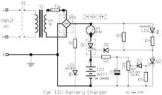
12V Car Battery Charger
Most car battery chargers are simple devices that continuously charge the battery with a few amperes for the duration it is ON. If the charger is not switched OFF in time, the battery will overcharge, its electrolyte lost due to evaporation, and its plate-element will likely be destroyed.

The 12 volt car battery charger circuit below will eliminate these problems by monitoring the batteries condition of charge through its retroactive control circuit by applying a high charge current until the battery is completely charged. When charging is complete, it turns on the red LED (LD2) and deactivates the charging circuit. This circuit is drawn to charge 12V batteries ONLY. Certain emphasis should be taken when wiring up this circuit. They are the connections of the transformer to the circuit board, and those supplying current to the battery being charged. These connections should be made with cables having a large cross-sectional area to prevent voltage-drop and heat build-up when current flows through them. See


Automatic 12V Lead Acid Battery Charger
This battery charger will charge any 12V lead acid battery including flooded, gel and AGM. It is fully automatic and will charge at a rate up to about 4A until the battery voltage reaches a preset point at which it will switch to a very low current float charge. If the battery voltage drops again the charger will begin charging until the voltage once again reaches the cut off point. In this way it can be left connected to a battery indefinitely to maintain full charge without causing damage. An LED indicates when the battery is fully charged.


You may be interested in reading: Power Adapters or Power Supplies

Rechargeable Charger and Batteries


There are four types of rechargeable batteries: nickel metal-hydride (NiMH), nickel cadmium (NiCad), rechargeable alkaline, and lithium ion.. They come in many different sizes and use different combinations of chemicals. And commonly used secondary cell chemistries are lead acid, nickel cadmium (NiCad), nickel metal hydride (NiMH), lithium ion (Li-ion), and lithium ion polymer (Li-ion polymer).


Types of Rechargeable Batteries
NiMH rechargeable batteries typically perform better than NiCads and are free of toxic heavy metals. Generally speaking, NiMH is the best all-around choice for most rechargeable battery applications. As an added bonus, most NiMH battery charger systems can accommodate NiCad batteries too (although the opposite is not true).

NiCads are being phased out in favor of NiMHs not only because they are losing the performance war, but also because of their inconvenience; the heavy metals used within the NiCad are toxic and require special disposal needs.

Rechargeable alkaline batteries have only two real advantages over NiMHs and NiCads: low cost and no need for special recycling. Otherwise, their long-term performance and recharge characteristics make these batteries a poor choice. Rechargeable alkaline batteries also require a special charger, which reminds me: don’t ever confuse rechargeable alkalines with the typical disposable alkaline batteries that are sold everywhere from 99-cent stores to the local grocery market – although some people do it, those batteries cannot be safely charged.

Lithium Ion batteries have great performance and can go unused for long periods without losing their charge. The big drawback is their price; not only are lithium ion batteries much more expensive than other types of rechargeable batteries, but they also require a special charger. Use them for rarely-used or high-drain devices like laptop computers, digital cameras, cell phones or portable television

Rechargeable Batteries Comparison Table
Here is a trade summary of the four basic options to help you decide which rechargeable battery is right for you. (lenpenzo dot com)


Click image to enlarge

Battery Charger
The energy used to charge rechargeable batteries mostly comes from AC current (mains electricity) using an adapter unit. Most battery chargers can take several hours to charge a battery. Most batteries can be charged in far less time than the most common simple battery chargers are capable of. Duracell and Rayovac now sell chargers that can charge AA- and AAA-size NiMH batteries in just 15 minutes; Energizer sells chargers that can additionally charge C/D-size and 9 V NiMH batteries. However, high rates of charging (eg. 15 minute charger, 1 hour chargers) will cause long term damage to NiMH and most other rechargeable batteries.


Best Battery Charger

Rechargeable batteries are susceptible to damage due to reverse charging if they are fully discharged. Fully integrated battery chargers that optimize the charging current are available.

Also, attempting to recharge non-rechargeable batteries has a small chance of causing a battery explosion.

Find on Amazon Rechargeable Batteries and Charger

Latest Student DC Power Supply


Here's a simple DC power supply having three output terminals: regulated +5VDC, unregulated +10VDC and 7.5VAC. The supply is suitable for microcontroller experimenting for any student.


My workbench has many broken devices and most of them will be used as the part for making the electronic projects. One day I looked at the broken radio, I found there's an AC line cord with socket and a transformer. Actually I like the way they used AC socket with the AC cord. I thought why don't make a simple DC supply from these parts. Most of the DC adapters provide only DC output. But not AC output, some of the uC circuit need a +5V for digital circuit, some need an AC line voltage for timing synchronization, digitizing sine wave, and some need unregulated for relay driving. So I designed above circuit for lab usage.

The DC power supply circuit is a linear regulator providing galvanic isolation from main line through the use of isolation transformer. Quite safe for experimenting with AC voltage. Below pictures show the example of input/output terminal connections, labeling and components placement in the box. The circuit can be built using universal PCB. The output terminal is for big load connection so this makes it quite strong and good electrical contact to the load being used.


Simple DC Power Supply for Students

RF Oscilator Basic Explnation and Circuit


This basic oscillator circuit is easy to build and the components are not critical. Most of them can be found in your junk parts box. The L1 antenna coil can be made by close winding 8-10 turns of 22 gauge insulated hookup wire around 1/4" form such as pencil.

You can experiment with the size of the coil and the number of turns to see how it affects frequency and signal output of the oscillator. And the next stage is to try changing the transistor type.

You should be able to pick up its signal with a standard fm radio receiver. The "signal in" should be coupled with a disc capacitor of about 0.1 uf to the stage in front of it.


More of Basic RF Oscilator

Latest Low Voltage, High Current Time Delay Circuit


In this circuit a LM339 quad voltage comparator is used to generate a time delay and control a high current output at low voltage. Approximatey 5 amps of current can be obtained using a couple fresh alkaline D batteries. Three of the comparators are wired in parallel to drive a medium power PNP transistor (2N2905 or similar) which in turn drives a high current NPN transistor (TIP35 or similar). The 4th comparator is used to generate a time delay after the normally closed switch is opened. Two resistors (36K and 62K) are used as a voltage divider which applies about two-thirds of the battery voltage to the (+) comparator input, or about 2 volts. The delay time after the switch is opened will be around one time constant using a 50uF capacitor and 100K variable resistor, or about (50u * 100K) = 5 seconds. The time can be reduced by adjusting the resistor to a lower value or using a smaller capacitor. Longer times can be obtained with a larger resistor or capacitor. To operate the circuit on higher voltages, the 10 ohm resistor should be increased proportionally, (4.5 volts = 15 ohms).

Source : http://ourworld.compuserve.com/homepages/Bill_Bowden/

5 DOT LED LINEAR LEVEL METER DRIVER circuit using KA2284 5 DOT LED LINEAR LEVEL METER DRIVER circuit using KA2287 5 DOT LED LINEAR LEVEL METER DRIVER circuit using KA2284 5 DOT LED LINEAR LEVEL METER DRIVER circuit using KA2284 The KA2284 are a monolithic integrated circuit disigned for 5-dot LED level meter drives with a built-in rectifying a amplifier, it is suitable for AC/DC level meters such as VU meters or signal meters. FEATURES High gain rectifying amplifier included (Gv= 26dB). Low radiation noise when LED turns on. Linear indicator for 5-dot LED of bar type. Constant current output. KA2284 :Io= 15mA Typ. Wide operating supply voltage range: Vcc= 3.5V~16V. Minimum number of external parts required. Published May 19, 2010 & Filed in Led Tags: 5, Circuit, DOT, driver, external, KA2284, KA2285, KA2287, LED, level, linear, meter, Parts, required.


5 DOT LED LINEAR LEVEL METER DRIVER circuit using KA2284
5 DOT LED LINEAR LEVEL METER DRIVER circuit using KA2287
5 DOT LED LINEAR LEVEL METER DRIVER circuit using KA2284
The KA2284 are a monolithic integrated circuit disigned for 5-dot LED level meter drives with a built-in rectifying a amplifier, it is suitable for AC/DC level meters such as VU meters or signal meters.
FEATURES
High gain rectifying amplifier included (Gv= 26dB).
Low radiation noise when LED turns on.
Linear indicator for 5-dot LED of bar type.
Constant current output.
KA2284 :Io= 15mA Typ.
Wide operating supply voltage range: Vcc= 3.5V~16V.
Minimum number of external parts required.

Building a Wireless Infrared Alarm An infrared alarm is an alarm that works via infrared. Infrared is used as a sensor, from an infrared transmitter


Building a Wireless Infrared Alarm

An infrared alarm is an alarm that works via infrared. Infrared is used as a sensor, from an infrared transmitter to the receiver. When infrared rays are blocked by people who passing through it, the alarm will activate a buzzer. This Alarm
is suitable for use in a corridor or small gate to detect people through the door.
Because the media used is an infrared light so that this infrared alarm is also said as a wireless infrared alarm. Infrared alarm system is qui
te simple and easy to build by using some 555 timer IC with infrared sensors LD274 for the transmitter and SFH5110 for the receiver.
Infrared signal emitted by the transmitter is not carried out continuously. Instead, it is modulated on the carrier frequency of 36 KHz to pulse t
he IRED (Infrared Emitting Diode) on and off itself, is switched on and off at a rate of about 300 Hz. This is done because most of the infrared sensors, including infrared alarm suggested in this diagram does not respond well to the incident infrared light continuously.
This infrared alarm circuit is not designed per
fectly, still need to add filtering so as not to be affected by direct sunlight. This need for a receiver to receive the infrared sensor with good intensity. This infrared alarm system is also designed for distances of several meters, and for those of you of course is quite challenging if you can make an even more powerful.
Infrared Alarm Transmitter and Re
ceiver Circuit
The infrared transmitter consists of two oscillators built around TLC555 IC. IC1 is the 300-Hz generator, IC2, the 36-kHz source. The IRED type LD274 is pulsed at a relatively high peak current via driver transistor T1. If i
n your application the distance covered by the IR beam is relatively short, the value of resistor R5 may be increased to save on current consumption. Preset P1 is adjusted for a carrier frequency of 36 kHz exactly (failing test equipment, adjust it for the optimum range).


Wireless Infrared Alarm-Transmitter Receiver Circuit
The receiver is equally simple and also based on a CMOS 555. As long as the sensor picks up infrared light from the transmitter, the reset input of the 555 IC is held low and the buzzer is silent. Components D1 and C2 act as a low-frequency rectifier to cancel the effect of the 300 Hz modulation on the transmitter signal. When the infrared light beam is interrupted, the oscillator built around the 555 is enabled and starts to produce a warning tone.
The test values indicated in the infrared barrier alarm circuit diagram are average DC levels measured with a Digital Volt Meter, under light/no light conditions. In fact, most test points carry rectangular or sawtooth waveforms.

DC Laptop Computer PSU/Adapter for Car Operate your laptop from a car can be done easily if you have a DC to DC Converter, namely a power supply devi


Operate your laptop from a car can be done easily if you have a DC to DC Converter, namely a power supply device for changing a DC voltage into another DC voltage is greater (step-up) or smaller (step-down). Changes in output voltage is usually followed by changes that accompany the current. This Step-up DC-DC converter circuit is to be more easily understood, then known as a laptop computer PSU/adapter for the car.
Laptop Computer PSU (Power Supply Unit) to change the voltage of DC adapter car battery to keep the output voltage of about 19V DC with a tolerance of +/ – 0.5V. Input voltage required by the car battery adapter for laptops this can work well between 9.2V-15V, and can supply 5A continuous current with brief excursions up to 10A.
Car Laptop Computer PSU Circuit Schematic
Laptop computers PSU using SMPS Controller IC UC3843 in the design, which is the fixed frequency current-mode PWM controller. It’s specially designed for Off-Line and DC to DC converter applications with minimum external components. For the voltage amplifier transistors, a pair BD139/BD140 used as a driver for strengthening the IRL2505 MOSFET final transistor.
Use a car cigarette lighter socket on a voltage input section and just plug into the socket. Then use a standard laptop voltage connector and connect at the output voltage circuit. The next step is measuring the voltage output on a laptop computer PSU/adapter circuit. If there is a nominal voltage of 19V DC, the computer PSU is ready for use.

Latest Circuit Barking Dog Alarm Circuit When your dog barks constantly at night, surely crossed your mind that there is something you do not know. D


When your dog barks constantly at night, surely crossed your mind that there is something you do not know. Dogs have the ability to adapt situations to maximize the sensitivity of night vision in low light. Warnings from the barking dog are an early warning of a Barking dog alarm, by utilizing the ability of dogs to see the object
moving than at rest in the dark.
Barking dog alarm is going to use the voice captured through a condenser microphone and ultimately will turn on the lights in a certain time interval where as if the occupants had been notified. Alarm circuit is very useful and can be placed in a dog cage. The alarm is quite easy to build and is something pretty good idea.
How Barking Dog Alarm Works
Condenser microphone (the alarm) mounted in the dog’s cage will perceive the sound bark and produces an AC signal, which pass through the DC blocking capacitor C1 to the base of transistor BC549 (T1). Transistor T1 with T2 will strengthen the voice signal and provide current pulses from the collector of T2. Trigger input pulses applied to the collector of transistor T3 and combined with capacitor C3 to the base of the transistor T4, which causes the T4 Cutt-off. The collector voltage of transistor T4 forward biases transistor T3 through resistor R8.
Barking Dog Alarm Circuit Barking Dog Alarm Circuit
Transistor T1 conducts and capacitor C3 discharges to keep transistor T4 cut-off. Transistor T4 remains cut-off until capacitor C3 charges enough to enable it to conduct. When transistor T4 conducts, its collector voltage goes low to drive transistor T3 into cut-off state. Resistor R9 and capacitor C3 are timing components. When fully charged, capacitor C3 takes about two minutes to discharge. So when sound is produced in front of the condenser mic, TRiAC1 (BT136) fires and the bulb (B1) glows for about two minutes.
Assembly Instruction
Assemble the barking dog alarm circuit on a general-purpose PCB and enclose in a plastic cabinet. Power supply to the circuit can be derived from a 12V, 500mA step-down transformer with rectifier and smoothing capacitor. Solder the triac ensuring sufficient spacing between the pins to avoid short circuit. Fix the unit in the dog’s cage, with the lamp inside or outside as desired. Connect the microphone to the circuit using a short length of shielded wire. Enclose the microphone in a tube to increase its sensitivity.
Warning
Since the circuit uses 220V AC, many of its points are at AC mains voltage. it could give you lethal shock if you are not careful. So if you don’t know much about working with line voltages, do not attempt to construct this circuit. Any kind of resulting loss or damage will be your responsible. (Taken from Night Alert by D. Mohan Kumar)

LM338 5A Adjustable Voltage Power Supply circuit and explanation


Here’s a variable voltage power supply circuit using a LM338 adjustable 3 terminal regulator to supply a current of up to 5A over a variable output voltage of 2V to 25V DC. It will come in handy to power up many electronic circuits when you are assembling or building any electronic devices. The schematic and parts list are designed for a power supply input of 240VAC. Change the ratings of the components if 110V AC power supply input is required.

2-25V Power Supply Schematic

The mains input is applied to the circuit through fuse F1. The fuse will blow if a current greater than 8A is applied to the system. Varistor V1 is used to clamp down any surge of voltage from the mains to protect the components from breakdown. Transformer T1 is used to step down the incoming voltage to 24V AC where it is rectified by the four diodes D1, D2, D3 and D4. Electrolytic capacitor E1 is used to smoothen the ripple of the rectified DC voltage.

Diodes D5 and D6 are used as a protection devices to prevent capacitors E2 and E3 from discharging through low current points into the regulator. Capacitor C1 is used to bypass high frequency component from the circuit. Ensure that a large heat sink is mounted to LM338 to transfer the heat generated to the atmosphere.

Source: 2- 25V 5A Power Supply LM338

On Off Touch Switch Circuit with Photo Transistor using 40106B On Off Touch Switch Circuit with Photo Transistor using 40106B On Off Touch Switch C


On Off Touch Switch Circuit with Photo Transistor using 40106B

On Off Touch Switch Circuit with Photo Transistor using 40106B

On Off Touch Switch Circuit with Photo Transistor using 40106B

Latest simple Loudspeaker Protection Circuit and explanation


Loudspeaker Protection Circuit is really simple, but the function Loudspeaker Protection Circuit is very important, because the Loudspeaker Protection will provide protection to Loudspeaker and other component. Because if the DC current flowing to the speakers must be disconnected as soon as possible. There are several issues that need to be resolved to ensure that the Safety Circuit Speaker will happen fast enough to stop the loudspeaker so that it is not broke, Loudspeaker Protection Circuit is also used to slow the response to damage.
Sometimes other people just simply uses the fuse but remain less effective, Loudspeaker Protection Circuit also includes mute function, which left the sound off and disconnects the speaker as soon as possible after power is switched off to prevent damage Loudspeaker.
Loudspeaker Protection Circuit Using Speaker relay as shown below. Although the circuit looks simple Loudspeaker Protection Circuit, Loudspeaker Protection Circuit but this principle is the same with the factory-made.
For practical purposes, Loudspeaker Protection Circuit has a low frequency limit of 20Hz, and this mean that the minimum 25ms delay is very important. In fact, the combination of low frequency, and waveform asymmetry on the higher frequency, larger delays are usually required. For this reason, it is important that the Loudspeaker Protection Circuit can be easily modified, to change the initial time delay before the system detects the DC and decided Loudspeaker.
Loudspeaker Protection Circuit be able to detect either polarity DC offset, and become immune to the effect of asymmetric waveform and a low frequency, Loudspeaker Protection Circuit is a common requirement, and it is most prudent to use
Loudspeaker Protection Circuit is simple and works well, and as indicated will not trigger a 30V RMS signal at 5Hz, but operates on 30V DC with 60ms applied, and in 50mS with a 45V supply .
Loudspeaker Protection Circuit is not only for Loudspeaker Protection Circuit also suitable for our needs, such as a symmetrical, and with the input diode as shown, a single detector can be used with several input amps and different time constants for each filter.
Loudspeaker Protection Circuit

The basic medium wave circuit Transmissions on Medium Wave frequencies are by Amplitude Modulation. …. On this basis, if used in our receiver circu


The basic medium wave circuit

Transmissions on Medium Wave frequencies are by Amplitude Modulation. …. On this basis, if used in our receiver circuit


Latest Mini fm radio Transmitter circuit and Description


Mini fm radio Transmitter circuit

Mini fm radio Transmitter circuit using BF199

This small FM transmitter with a range of about 50 meters designed for hoby. With lots of mini-transmitters then you have a comprehensive, action-packed radio program. Due to the power supply via the USB port of a high frequency stability is achieved. Alternatively, the receiver, a battery 5 to 12 volts to operate.

Burglar Alarms circuit and explanation For those who want the effort to prevent theft in the neighborhood, home burglar alarms become an important t


Burglar Alarms circuit and explanation

For those who want the effort to prevent theft in the neighborhood, home burglar alarms become an important tool. To realize an alarm s

ystem for your home can be complicated and expensive. Many home security systems are offered ranging from sirens to the video monitor, but still must consider the cost should be excluded.

This page does not mean to do not care about safety, just trying to explain in simple information on how to design home burglar alarms base

d on the following circuit with several features that are pretty good if you want to build it.

Simple Home Burglar Alarm Circuit

The following home burglar alarm circuit using the active components 4011 CMOS IC and transistor BC547 with features, including automatic Exit and Entry delay and timed Bell / Siren Cut-Off. This home burglar alarm circuit is des

igned for use with the ordinary-type input device is usually covered such as – magnetic reed contacts – micro switches – foil tape – and PIRs.

Home Burglar Alarm Circuit

Home Burglar Alarm Circu

it Parts List

Transistor BC547
Diodes 1N4148
CMOS 4011
Capacitor Electrolytic 25 Volt
C2 100 uF

C3 220 uF
C5 100 uF
Capacitors Ceramic 63 Volt
C1 100n

C4 100n
Resistor 0.25 watt
3 x 1k
4 x 2k7
2 x 330k
1 x 4M7

Simple Home Burglar Alarm Using SCR

This home burglar alarm circuit is a loud alarm at the break of the daylight. It uses a 555 timer IC that has a function as an astable multivibrator at a frequency of about 1kHz. Home burglar alarm is placed in a specific space, like cupb

oards as an anti-burglar alarm. The alarm is activated when the cupboard is open when the light will hit the circuit.


Anti Burglar Alarm-Light Sensor

When no light falls on the LDR, the transistor is pulled high by the variable resistor. Hence the transistor is OFF and the reset pin of the 555 is pulled low. Due the this the 555 is reset. When light falls on the LDR, its resistance decreases and pulls the bases of the transistor low hence turning it ON. This pulls the reset pin 4 of the 555 high and hence enables the 555 oscillator and a sound is produced by the speakers. The 100K variable resistor has to be adjusted to set the light intensity that triggers the alarm.

Latest Motion Sensor Outdoor Lighting circuit and Explanation Motion sensors can be interpreted independently represents a measure of change in mot


Motion sensors can be interpreted independently represents a measure of change in motion that can be a vector and / or velocity of an object or an object in a field of view where there is a physical interaction between mechanical equi

pment with a field of view. From this point, we will determine what the desired outcome interaction. What about Motion sensor outdoor lighting?

Halogen Motion Sensor Outdoor Lighting

I am sure, that depart from our

understanding of the motion sensor. Motion sensor outdoor lighting gives an indication to us that there is an interaction between a motion sensor to a situation out there where the activation of a light beam is expected.

Motion Sensor Outdoor Lighting is very useful for those requiring a light beam. This motion sensor can be used as a light

alarm that can give a surprise to people who are not invited to that are in your yard.

Even the motion sensor outdoor lighting will help you when to go home at night, carrying a lot of shopping items in your hands, with low light conditions. Well, you know what is meant by it.

Motion Sensor Outdoor Lighting is one type of alarm circuits that is widely available market price of about $ 40. However,

on this occasion will be explained in a fundamental fact about what is in a motion sensor outdoor lighting box, so you can be a little bright on this.

Motion Sensor Switch Circuit

The main components of a motion sen

sor outdoor lighting is a Passive Infrared (PIR transducer), BS170 Mosfet transistor as the high-gain amplifier (switch), Relay 12V DC as the AC power switch and some diodes, resistors, electrolytic capacitors, and input / output AC terminals to the lamp.


Motion Sensor Outdoor Lighting-Switch

Select a PIR sensor unit in accordance with the required sensing distance, you can contact the nearest vendor, select ready-made box type. Relay type is selected in accordance with the lamp load. However, this also will affect the transistor mosfet as a switch. Since this is aimed at light load, then you need to modify the power transistor.

In a test using 12V DC lamp types. If the motion sensor circuit is functioning as you need to put a PIR motion sensor module by considering the source of motion, for example, regarding human height and adjust the height placement module.

Each time the PIR module detects movement of a living body. The output relay and switching mosfet in the circuit is switched to the part through 150 Ohm resistor and associated components. As a result, the relay on the output transistor is switched on and the lights get power supply through a relay (RL) contacts.

Motion sensor outdoor lighting is only, as an illustration, not recommended for those of you do not have enough knowledge of electronics, because this will your safety concerns related to AC power.

Charge Balance converter circuit


AD7711 IC for Charge Balance converter circuit

AD7711 IC for Charge Balance converter circuit

AD7711 IC for Charge Balance converter circuit

TV remote control blocker using 555 ON electronic circuits diagrams TV remote control blocker TV remote control blocker


TV remote control blocker using 555 ON electronic circuits diagrams

TV remote control blocker

TV remote control blocker

RF preamp Circuits using CD4007. RF Preamp properly tune CD4007 Audio Preamplifier Circuits and Design Guidelines for Bipolar rf preamp Circuits r


RF preamp Circuits using CD4007.

RF Preamp properly tune CD4007 Audio Preamplifier Circuits and Design Guidelines for Bipolar

rf preamp Circuits

rf preamp Circuits

Making Charger Battery


Making Charger Battery

Making Charger Battery

Rc servo controller circuit using PIC18F252 rc servo controller circuit rc servo controller circuit


Rc servo controller circuit using PIC18F252

rc servo controller circuit

rc servo controller circuit

Microcontroller power supply circuit using mosfet


Microcontroller power supply circuit using mosfet

on any cell charger phone circuit using 74C14, IRFZ48Z

cell charger phone circuit

cell charger phone circuit

If you want to report any meterial please