RGB To Color Difference Converter circuit and explanation


The circuit diagram shows two LT1398’s from Linear Technology used to create buffered color-difference signals from RGB (red-green-blue) inputs. In this application, the R input arrives via 75Ω coax. It is routed to the non-inverting input of amplifier IC1a and to 1.07-kΩ resistor, R8. There is also an 80.6-Ω termination resistor R11, which yields a 75-Ω input impedance at the R input when considered in parallel with R8. R8 connects to the inverting input of a second LT1398 amplifier (IC1b), which also sums the weighted G and B inputs to create a –0.5Y output.

RGB To Color Difference Converter circuit diagramYet another LT1398 amplifier, IC2a, then takes the –0.5Y output and amplifies it by a gain of –2, resulting in the +Y output. Amplifier IC1a is configured for a non-inverting gain of 2 with the bottom of the gain resistor R2 tied to the Y output. The output IC1a thus results in the color-difference output R–Y. The B input is similar to the R input. Here, R13 when considered in parallel with R10 yields a 75-Ω input impedance. R10 also connects to the inverting input of amplifier IC1b, adding the B contribution to the Y signal as discussed above.

PSU RGB To Color Difference ConverterAmplifier IC2b is configured to supply a non-inverting gain of 2 with the bottom of the gain resistor R4 tied to the Y output. The output of IC2b thus results in the color-difference output B–Y. The G input also arrives via 75-Ω coax and adds its contribution to the Y signal via resistor R9, which is tied to the inverting input of amplifier IC1b. Here, R12 and R9 provide the 75Ω termination impedance. Using superposition, it is straightforward to determine the output of IC1b. Although inverted, it sums the R, G and B signals to the standard proportions of 0.3R, 0.59G and 0.11B that are used to create the Y signal. Amplifier IC2a then inverts and amplifies the signal by 2, resulting in the Y output. The converter draws a current of about 30mA from a symmetrical 5-volt supply.

VGA to BNC Adapter Converter Circuit and explanation


There are monitors which only have three BNC inputs and which use composite synchronization (‘sync on green’). This circuit has been designed with these types of monitor in mind. As can be seen, the circuit has been kept very simple, but it still gives a reasonable performance. The principle of operation is very straightforward. The RGB signals from the VGA connector are fed to three BNC connectors via AC-coupling capacitors. These have been added to stop any direct current from entering the VGA card. A pull-up resistor on the green output provides a DC offset, while a transistor (a BS170 MOSFET) can switch this output to ground. It is possible to get synchronisation problems when the display is extremely bright, with a maximum green component.

In this case the value of R2 should be reduced a little, but this has the side effect that the brightness noticeably decreases and the load on the graphics card increases. To keep the colour balance the same, the resistors for the other two colors (R1 en R3) have to be changed to the same value as R2. An EXOR gate from IC1 (74HC86) combines the separate V-sync and H-sync signals into a composite sync signal. Since the sync in DOS-modes is often inverted compared to the modes commonly used by Windows, the output of IC1a is inverted by IC1b. JP1 can then by used to select the correct operating mode. This jumper can be replaced by a small two-way switch, if required.


This switch should be mounted directly onto the PCB, as any connecting wires will cause a lot of interference. The PCB has been kept as compact as possible, so the circuit can be mounted in a small metal (earthed!) enclosure. With a monitor connected the current consumption will be in the region of 30 mA. A 78L05 voltage regulator provides a stable 5 V, making it possible to use any type of mains adapter, as long as it supplies at least 9 V. Diode D2 provides protection against a reverse polarity. LED D1 indicates when the supply is present. The circuit should be powered up before connecting it to an active VGA output, as otherwise the sync signals will feed the circuit via the internal protection diodes of IC1, which can be noticed by a dimly lit LED. This is something best avoided.

Resistors:
R1,R2,R3 = 470Ω
R4 = 100Ω
R5 = 3kΩ3
Capacitors:
C1,C3,C5 = 47µF 25V radial
C2,C4,C6,C7,C10 = 100nF ceramic
C8 = 4µF7 63V radial
C9 = 100µF 25V radial
Semiconductors:
D1 = LED, high-efficiency
D2 = 1N4002
T1 = BS170
IC1 = 74HC86
IC2 = 78L05
Miscellaneous:
JP1 = 3-way pinheader with jumper
K1 = 15-way VGA socket (female), PCB mount (angled pins)
K2,K3,K4 = BNC socket (female), PCB mount, 75Ω

220V AC Lamp Toggle Switch Circuit


Compact, transformerless circuitry No relays employed


Due to the low current drawing, the circuit can be supplied from 230Vac mains without a transformer. Supply voltage is reduced to 12Vdc by means of C1 reactance, a two diode rectifier cell D1 & D2 and Zener diode D3. IC1A, IC1B, R2, R3 and C3 form a reliable bounce-free toggle switch operated by P1. R4 and C4, wired to pin #6 of IC1B reset the circuit (lamp off) when power supply is applied. IC1C and IC1D wired in parallel act as a buffer, driving the Gate of the Triac through R5.


Circuit diagram:


220V AC Lamp Toggle Switch Circuit Diagram


Parts:

R1 = 470R
R2 = 10K
R3 = 100K
R4 = 100K
R5 = 1K
C1 = 330nF-400V
C2 = 100uF-25V
C3 = 100nF-63V
C4 = 10uF-25V
D1 = 1N4007
D2 = 1N4007
D3 = BZX79C12
D4 = TIC206M
IC1 = 4011 NAND Gate


Notes:
  • The circuit can be wired permanently to the mains supply as current drain is negligible.
  • Due to transformerless design there is no heat generation.
  • Low Gate-current Triacs are recommended.
  • Obviously, other appliances can be powered in place of a lamp, provided their power dissipation does not exceed about 400W @ 230V
  • 110-120Vac operation is easily obtained by simply changing C1 value to 680nF 250V. No further changes are necessary.
  • In some cases, e.g. when the controlled device is far from the toggle switch, a pilot LED could be necessary for monitoring purposes. If so, disconnect pin #10 of IC1C from pin #11 of IC1D and wire a LED and its 1K series current limiting resistor across pin #10 of IC1C and negative supply.
  • Warning! The circuit is connected to 230Vac mains, so some parts in the circuit board are subjected to lethal potential! Avoid touching the circuit when plugged in and enclose it in a plastic box.
  • P1 will SPST Pushbutton

Temperature Sensitive Switch For Solar Collector circuit and explanation


This circuit can be used to turn the pump on and off when a solar collector is used to heat a swimming pool, for example. This way the water in the collector has a chance to warm up significantly before it is pumped to the swimming pool. A bonus is that the pump doesn’t need to be on continuously. The basis of operation is as follows. When the temperature of the water in the solar collector is at least 10 °C higher than that of the swimming pool, the pump starts up.

The warm water will then be pumped to the swimming pool and the temperature difference will drop rapidly. This is because fresh, cool water from the swimming pool enters the collector. Once the difference is less than 3 °C the pump is turned off again. R10/R1 and R9/R2 each make up a potential divider. The output voltage will be about half the supply voltage at a temperature around 25 °C. C7 and C8 suppress any possible interference.

The NTCs (R9 and R10) are usually connected via several meters of cable, which can easily pick up interference. Both potential dividers are followed by a buffer stage (IC1a/IC1b). IC1c and R3, R4, R5 and R6 make up a differential amplifier (with unit gain), which measures the temperature difference (i.e. voltage difference). When both temperatures are equal the output is 0 V. When the temperature of the solar collector rises, the differential amplifier outputs a positive voltage.

This signal is used to trigger a comparator, which is built round an LM393 (IC2a). R7 and P1 are used to set the reference voltage at which the comparator changes state. R8 and P2 provide an adjustable hysteresis. R11 has been added to the output of IC2a because the opamp has an open collector output. A power switch for the pump is created by R12, T1 and Re1. D1 protects T1 against voltage spikes from the relay coil when it is turned off.

A visual indication of the state of the controller is provided by IC4 (UAA170), a LED spot display driver with 16 LEDs. The reference voltage for the comparator is buffered by IC1d and fed to input VRMAX of the UAA170. R20/D21 and R23/D22 limit the input voltages of IC4 to 5.1 V, since the maximum permissible input voltage to the UAA170 is 6 V. When there is no temperature difference, LED D20 turns on.

Circuit diagram:
Temperature Sensitive Switch For Solar Collector circuit schematic
Temperature Sensitive Switch Circuit Diagram For Solar Collector

As the temperature difference increases the next LED turns on. The full scale of the LED bar is equal to the reference voltage of the comparator. This means that when the last LED (D5) of the UAA170 turns on, the comparator switches state. This is also indicated by D2. The power supply has been kept fairly simple and is built around a LM7812 regulator. The circuit is protected against a reverse polarity at the input by D3.

You have to make sure that the input to the regulator is at least 15 V, otherwise it won’t function properly. There are a few points you should note regarding the mounting of the NTCs. NTC R9 should be placed near the output of the solar collector. You should choose a point that always contains water, even when some of the water flows back a little. NTC R10 should be mounted inside the filter compartment (where it exists), which continually pumps the swimming pool water.

This will give a good indication of the temperature of the water. The way the circuit has to be set up depends how it has been installed and is very much an experimental process. To start with, set hysteresis potentiometer (P2) halfway. Then set the reference voltage to about 1.5-2 V with P1. On a sunny day you can measure the voltage difference to get an idea as to which reference voltage needs to be adjusted. The hysteresis setting determines how long the pump stays on for, which is until the minimum temperature difference has been reached.
Author: Tom Henskens - Copyright: Elektor Electronics Magazine

RC (Remote Control) Switch


It is sometimes necessary for an RC (remote control) model to contain some kind of switching functionality. Some things that come to mind are lights on a model boat, or the folding away of the undercarriage of an aeroplane, etc. A standard solution employs a servo, which then actually operates the switch. Separate modules are also available, which may or may not contain a relay. A device with such functionality is eminently suitable for building yourself. The schematic shows that it can be easily realised with a few standard components.

Picture of the project:
RC (Remote Control) Switch circuit
RC Switch Circuit

The servo signal, which consists of pulses from 1 to 2 ms duration, depending on the desired position, enters the circuit via pin 1 of connector K1. Two buffers from IC2 provide the necessary buffering after which the signal is differentiated by C2. This has the effect that at each rising edge a negative start signal is presented to pin 2 of IC1. D1 and R4 make sure that at the falling edge the voltage at pin 2 of IC2 does not become too high. IC1 (TLC555) is an old faithful in a CMOS version.

A standard version (such as the NE555) works just as well, but this IC draws an unnecessarily high current, while we strive to keep the current consumption as low as possible in the model. The aforementioned 555 is configured as a one-shot. The pulse-duration depends on the combination of R2/C1. Lowering the voltage on pin 5 also affects the time. This results in reducing the length of the pulse. In this circuit the pulse at the output of IC will last just over 1.5 ms when T1 does not conduct.

Circuit diagram:
RC (Remote Control) Switch circuit schematic
RC Switch Circuit Diagram

When T1 does conduct, the duration will be a little shorter than 1.5 ms. We will explain the purpose of this a little later on. Via IC2.C, the fixed-length pulse is, presented to the clock input of a D-flip-flop. As a consequence, the flip-flip will remember the state of the input (servo signal). The result is that when the servo-pulse is longer than the pulse form the 555, output Q will be high, otherwise the output will be low. It is possible, in practice, that the servo signal is nearly the same length as the output from the 555.

A small amount of variation in the servo signal could therefore easily cause the output to ‘chatter’, that is, the output could be high at one time and low the next. To prevent this chatter there is feedback in the form of R1, R3 and T1. This circuit makes sure that when the flip-flip has decided that the servo-pulse is longer than the 555’s pulse (and signals this by making output Q high), the pulse duration from the 555 is made a little shorter. The length of the servo-signal will now have to be reduced by a reasonable amount before the servo-pulse becomes shorter than the 555’s pulse.

Parts and PCB layout:
parts and pcb layout for RC (Remote Control) Switch circuit
Parts and PCB layout Of RC Switch

The moment this happens, T1 will stop conducting and the mono-stable time will become a little longer. The servo-pulse will now have to be longer by a reasonable amount before the flip-flip changes back again. This principle is called hysteresis. Jumper JP1 lets you choose between the normal or inverted output signals. Buffers IC2.D through to IC2.F together with R5 drive output transistor T2, which in turn drives the output. Note that the load may draw a maximum current of 100 mA. Diode D2 has been added so that inductive loads can be switched as well (for example, electrically operated pneu-matic valves).

COMPONENTS LIST
Resistors:
R1 = 470k
R2 = 150k
R3 = 47k
R4 = 100k
R5 = 4k7
Capacitors:
C1 = 10nF
C2 = 1nF
C3,C4 = 100nF
Semiconductors:
D1 = BAT85 or similar Schottky diode
D2 = 1N4148
IC1 = CMOS 555 (e.g., TLC555 or ICM7555)
IC2 = 4049
IC3 = 4013
T1,T2 = BC547B
Miscellaneous:
JP1 = jumper with 3-way pinheader
K1 = servo cable
K2 = 2-way pinheader or 2 solder pins
Author: Paul Goossens - Copyright: Elektor Electronics

Petrol Gas Switch For A Pajero circuit and explanation


My current vehicle, a Pajero, was modified for dual fuel - ie, petrol and gas. However, it's necessary to run the vehicle on petrol at regular intervals to stop the injectors from clogging up. This simple circuit allows the vehicle to be started using petrol and then automatically switches it to gas when the speed exceeds 45km/h and the brake pedal is pressed. Alternatively, the vehicle may be run on petrol simply by switching the existing petrol/gas switch to petrol. You can also start the vehicle on gas by pressing the brake pedal while starting the vehicle. The circuit is based on an LM324 dual op amp, with both op amps wired as comparators. It works like this: IC1a buffers the signal from the vehicle's speed sensor and drives an output filter network (D1, a 560kO resistor and a 10µF capacitor) to produce a DC voltage that's proportional to the vehicle's speed.

Circuit diagram:
Petrol gas switch for a Pajero circuit schematic

This voltage is then applied to pin 5 of IC1b and compared with the voltage set by trimpot VR1. When pin 7 of IC1b goes high, transistor Q1 turns on. This also turns on transistor Q2 when the brake pedal is pressed (pressing the brake pedal applies +12V from the brake light circuit to Q2's emitter). And when Q2 turns on, relay 1 turns on and its contacts switch to the gas position. Trimpot VR1 must be adjusted so that IC1b's pin 7 output switches high when the desired trigger speed is reached (ie, 45km/h). In effect, the speed signal is AND'ed with the brake light signal to turn on the relay. The vehicle has been running this circuit for several years now and is still running well, with no further injector cleans required.
Author: J. Malnar - Copyright: Silicon Chip Electronics

For Computers Speaker-Headphone Switch circuit and explanation


If you need to use a headset with your PC, then you will know how frustrating it is continuously swapping over speaker and microphone cables. This is even worse if the PC is parked in a dark corner and the hard-to-read writing on the sound card sockets is covered in dust. This simple switch box eliminates all these problems. It sits on top of the desk and connects to the PC with stereo one-to-one cables. On the rear of the box are sockets for the PC speaker and microphone connections and the existing speakers. On the front of the box are the sockets for the headset microphone and headphones, an input for an external microphone and two switches. One switch is used to direct the sound card output from the PC to either the existing speakers or the headphones.

Circuit diagram:
Speaker-headphone switch for PCs circuit schematic
Speaker-Headphone Switch Circuit Diagram For Computers

The second switch connects either the headset microphone or the external microphone to the input socket of the PC sound card. The switches used were 3 position 4 pole rotary switches with the last pole unused and adjusted for 2-position operation. All sockets were stereo 3.5mm types. This multiple switching arrangement is very flexible and is especially handy if you want to use an external microphone while monitoring with headphones. The ground wire as well as the left and right wires are all switched to prevent noise that could otherwise be induced into the microphone input through joining separate earths. For the same reason, a plastic case is used so that the earths of the sockets are not shorted together as would happen with a metal case. You will require two additional short stereo extension cables to connect the box to the PC.
Author: Leon Williams - Copyright: Silicon Chip Electronics

Remote Mains Switch Low-Voltage circuit and explanation


This circuit allows a 240V mains appliance to be controlled remotely via low-voltage cabling and a pushbutton switch. The mains appliance (in this case, a light bulb) is switched with a suitably-rated relay. All of the electronics is housed in an ABS box located in proximity to the appliance. The pushbutton switch and plugpack are located remotely and can be wired up with 3-core alarm cable or similar. Cable lengths of 20m or more are feasible with this arrangement. When the switch (S1) is pressed, the input (pin 8) of IC1c is briefly pulled low via the 10mF capacitor, which is initially discharged.

Circuit diagram:
Low-voltage remote mains switch circuit schematic
Low-Voltage Remote Mains Switch Circuit Diagram

The output (pin 10) immediately goes high and this is inverted and fed back to the second input (pin 9) via another gate in the quad NAND package (IC1d). In conjunction with the 1MW resistor and 470nF capacitor, IC1d eliminates the effects of contact "bounce" by ensuring that IC1c’s output remains high for a predetermined period. The output from IC1c drives the clock input of a 4013 D-type flip-flop (IC2). The flipflop is wired for a "toggle" function by virtue of the Q-bar connection back to the D input. A 2.2MW resistor and 100nF capacitor improve circuit noise immunity. Each time the switch is pressed, the flipflop output (pin 13) toggles, switching the transistor (Q1) and relay on or off. Note that all mains wiring must be properly installed and completely insulated so that there is no possibility of it contacting the low-voltage side of the circuit.
Author: Bob Hammond - Copyright: Silicon Chip Elecronics

On And Off Button circuit and explanation


In this simple circuit we give the chip a little more attention than usual. It is astonishing what can be built with a 555. We are always infatuated with simple circuits using this IC, such as the one shown here. The 555 is used here so that a single push-button can operate a relay. If you press the button once, the relay is energized. When you press it again the relay turns off. In addition, it is possible to define the initial state of the relay when the power supply is switched on. The design is, as previously mentioned, very simple. Using R1 and R2, the threshold and trigger inputs are held at half the power supply voltage.

Circuit diagram:
On-Off Button circuit schematic
On/Off Button Circuit Diagram

When the voltage at the threshold pin becomes greater that 2/3 of the power supply voltage, the output will go low. The output goes high when the voltage at the trigger input is less than 1/3 of the power supply voltage. Because C2, via R3, will eventually have the same level as the output, the output will toggle whenever the push-button is pressed. If, for example, the output is low, the level of the trigger input will also become low and the output will go high! C1 defines the initial state of the relay when the power is applied. If the free end of C1 is connected to Vcc, then the output is high after power up; the output is low when C1 is connected to ground.
Author: Ger Langezaal - Copyright: Elektor Electronics

The post is removed


Sorry
The post has been removed
to go to the original post kindly visit


http://www.emasta.com/2010/10/smart-foot-switch.html

Thanks

Automatic Switch For Voltage Converters


New applications for DC voltage converters, such as the ‘workhorse’ LT1070, arise every day. These converters can be adapted to nearly every imaginable ratio of input and output voltages. However, all of these circuits and devices have the same shortcoming, which is that they lack an on/off switch. Especially when they are used as a source of 6-V / 12-V power for a car radio, this is highly impractical. The circuit described here adds automatic load detection to the converter. For use in a car, the additional circuitry must be small and fit into a compact enclosure together with the converter.

Since the battery voltage and ambient temperature vary over wide ranges, a simple form of load detection must be used. Besides this, the voltage drop across the load sensing circuitry must naturally be as small as possible. This can be achieved by using ‘ultra-modern’ SiGe technology. The 6 V from the battery and the 12 V from the converter are combined in the MB R2545 dual diode. Consequently, a voltage of at least 6 V is always applied to the radio (for memory retention). If the radio is switched on, it draws a current from the 6-V battery, which may be around 100 mA.

This current produces a voltage across R1. If this voltage is 75 mV or greater, the AC128 germanium transistor starts conducting and charges electrolytic capacitor C1, which is connected to the gate of the BUZ10. The MOSFET energises RE1 and thus connects the supply voltage to the converter. As a result, 12-V power is connected to the radio. The resulting increased current causes the voltage drop across R1 to increase, which is undesirable, so a 10-A Schottky diode is connected in parallel. The total voltage drop is thus approximately 0.6 V. The RC network connected to the BUZ10 ensures that the transistor always remains switched on for at least several seconds, to prevent the circuit from ‘chattering’ with varying current consumption.

Automatic Switch Circuit Diagram For Voltage Converters

If the load is switched off, the AC128 cuts off, the electrolytic capacitor discharges and the relay again disconnects the voltage converter. The residual current consumption is so small that the circuit can also be connected ahead of the ignition switch. The Schottky diodes need only be rated for the necessary voltages and currents, and above all, they should have the lowest possible saturation voltage. The exact type is not critical. Two separate diodes can also be used. A small heat sink for the MBR diode won’t hurt, but this is normally not essential. Practically any type of PNP germanium transistor that is still available or on hand can be used (AC125, AC126 and AC128 work perfectly).

It may be necessary to modify the value of R1. In combination with the germanium transistor, R1 determines which level of current will be ignored (for memory retention) and which level of current will cause the converter to be switched on. With the component values shown in Figure 1, this level is between 10 mA and 25 mA. It is recommended to measure the quiescent current (at 6 V) and switch-on current of the load and then simulate the switching process using dummy load resistors. When selecting the 6-V relay, ensure that its contacts have an adequate current rating. The actual value can be significantly greater than the nominal output current. With a load of 5 A at 12 V and a converter efficiency of 70 percent, the current through the relay contacts rises to 14.3 A.
Author: C. Wolff
Copyright: Elektor Electronics

Microcontroller IR On/Off Switch circuit and explanation


Turn ON or OFF electrical devices using remote control is not a new idea and you can find so many different devices doing that very well. For realization of this type of device, you must make a receiver, a transmitter and understand their way of communication. Here you will have a chance to make that device, but you will need to make only the receiver, because your transmitter will be the remote controller of your tv, or video …This is one simple example of this kind of device, and I will call it IR On-Off or IR-switch.

How it works:

Choose one key on your remote controller (from tv, video or similar), memorized it following a simple procedure and with that key you will able to turn ON or OFF any electrical device you wish. So, with every short press of that key, you change the state of relay in receiver (Ir-switch). Memorizing remote controller key is simple and you can do it following this procedure: press key on Ir-switch and led-diode will turn ON. Now you can release key on Ir-switch, and press key on your remote controller. If you do that, led-diode will blink, and your memorizing process is finished.

Instructions:

To make this device will be no problem even for beginners in electronic, because it is a simple device and uses only a few components. On schematic you can see that you need microcontroller PIC12F629, ir-receiver TSOP1738 (it can be any type of receiver TSOP or SFH) and for relay you can use any type of relay with 12V coil.

click on the images to enlarge

Click here to download source code for PIC12F629-675 . To extract the archive use this password extremecircuits.net

Water Pump Relay Controller Circuit Schematic


Water reservoir automatic level control, Simple circuitry - 12V supply


By means of a Relay, employed to drive a water pump, this circuit provides automatic level control of a water reservoir or well. The shorter steel rod is the "water high" sensor, whereas the longer is the "water low" sensor. When the water level is below both sensors, IC1C output (pin #10) is low; if the water becomes in contact with the longer sensor the output remains low until the shorter sensor is reached. At this point IC1C output goes high, Q1 conducts, the Relay is energized and the pump starts operating.

Now, the water level begins to decrease and the shorter sensor will be no longer in contact with the water, but IC1C output will be hold high by the signal return to pin #5 of IC1B, so the pump will continue its operation. But when the water level falls below the longer sensor, IC1C output goes low and the pump will stop. SW1 is optional and was added to provide reverse operation. Switching SW1 in order to connect R3 to pin #11 of IC1D, the pump will operate when the reservoir is nearly empty and will stop when the reservoir is full. In this case, the pump will be used to fill the reservoir and not to empty it as in the default operating mode.


Circuit diagram:
 Water Pump Relay Control Schematic Circuit Diagram
Water Pump Relay Control Circuit Diagram


Parts:

R1 = 15K - 1/4W Resistors
R2 = 15K - 1/4W Resistors
R3 = 10K - 1/4W Resistor
R4 = 1K - 1/4W Resistor
D1 = LED - any type and color
D2 = 1N4148 - 75V 150mA Diode
Q1 = BC337 - 45V 800mA NPN Transistor
IC1 = 4001 Quad 2 Input NOR Gate CMos IC
SW = SPDT Toggle or Slide Switch (Optional)
RL1 = Relay with SPDT 2A @ 230V switch
Coil Voltage 12V - Coil resistance 200-300 Ohm
Two steel rods of appropriate length


Notes:
  • The two steel rods must be supported by a small insulated (wooden or plastic) board.
  • The circuit can be used also with non-metal tanks, provided a third steel rod having about the same height of the tank will be added and connected to the circuit's negative ground.

Momentary Switch Teamed With Latching Relay circuit and explanation


This circuit allows an SPST momentary pushbutton to act as a push-on push-off switch, using a DPDT latching (bi-stable) relay. It was originally intended to allow a single pushbutton switch on the dash of a vintage car to provide a latched function. The relay only draws current when it is being switched. At other times, the only current drain on the 12V supply is the leakage current of one 22µF capacitor, which is very low. It works as follows.

Assume that initially the latching relay is in the reset state, with pins 4 and 6 connected together. In this state, C2 charges up to +12V via 2.2kO resistor R2 while capacitor C1 remains discharged as it is not connected to the 12V supply. If S1 is pressed, C2 discharges via the relay’s “set” coil, diode D2 and S1. This switches the relay into its set position, connecting pins 4 and 8. C1 then begins to charge via R1. While S1 is being held down, the relay does not return to the reset position because the current supplied via R1 is insufficient for the coil to latch the armature. As soon as S1 is released, current no longer flows though the coil so C1 can finish charging, ready for the next button press.

Circuit diagram:
Momentary switch teamed with latching relay circuit schematic
Momentary Switch Circuit Diagram Teamed With Latching Relay

Once the relay has switched and C1 has finished charging, pressing S1 again causes the relay to switch back to the reset state via the same process. The unused set of relay contacts can be used as an SPST or SPDT switch. The circuit as shown has been tested with the Jaycar SY4060 relay. It will work with other DPDT twin-coil latching relays but the resistor and capacitor values may need to be adjusted to suit. Relays with lower resistance coils will need larger value capacitors and smaller value resistors.
Author: Merv Thomas - Copyright: Silicon Chip Electronics Magazine

Energy Saver Relay Coil circuit and explanation


Some relays will become warm if they remain energized for some time. The circuit shown here will actuate the relay as before but then reduce the ‘hold’ current through the relay coil current by about 50%, thus considerably reducing the amount of heat dissipation and wasted power. The circuit is only suitable for relays that remain on for long periods. The following equations will enable the circuit to be dimensioned for the relay on hand: R3 = 0.7 / I Charge time = 0.5 × R2 × C1 Where I is the relay coil current. After the relay has been switched off, a short delay should be allowed for the relay current to return to maximum so the relay can be energized again at full power. To make the delay as short as possible, keep C1 as small as possible. In practice, a minimum delay of about 5 seconds should be allowed but this is open to experimentation.

Circuit diagram:
Relay Coil Energy Saver circuit schematic
Relay Coil Energy Saver Circuit Diagram

The action of C2 causes the full supply voltage to appear briefly across the relay coil, which helps to activate the relay as fast as possible. Via T2, a delay network consisting of C1 and R2 controls the relay coil current flowing through T1 and R3, effectively reducing it to half the ‘pull in’ current. Diode D2 discharges C1 when the control voltage is Low. Around one second will be needed to completely discharge C1. T2 shunts the bias current of T1 when the delay has elapsed. Diode D1 helps to discharge C1 as quickly as possible. The relay shown in the circuit was specified at 12 V / 400 ohms. All component values for guidance only.
Author: Myo Min - Copyright: Elektor July-August 2004

Handy Time Delay With Relay Output circuit and explanation


This circuit is designed to provide delayed relay switching action at power on. The delay is a function of the time constant produced by the combination of R1 and C1. At power on, C1 charges slowly via R1 and the coil of the relay. When the voltage across C1 exceeds both the base-emitter voltage of Q1 and the gate trigger voltage of the SCR, gate current flows. This fires the SCR and switches on the relay. At power off, diode D1 rapidly discharges C1 through the 100O resistor, so ensuring that every time the circuit is restarted, as in a temporary outage, the delay time is maintained.

Circuit diagram:
time delay with relay output circuit schematic
Time Delay Circuit Diagram With Relay Output

Just about any NPN transistor can be used for Q1, since after SCR1 fires, it is effectively out of the circuit. In fact, the only part that’s still active after SCR1 turns on is the relay. You can’t get much simpler than that! This circuit can be used to delay speaker turn-on, so avoiding the "thump" that occurs in some stereo systems at power on. A 5-second delay is enough for this application, requiring approximately 560kO for R1 and 10µF for C1. Another application might be as a motor protector in a short power outage.
Author: R. Besana - Copyright: Silicon Chip Electronics

Relay Selector Pushbutton circuit and explanation


This circuit was designed for use in a hifi showroom, where a choice of speakers could be connected to a stereo amplifier for comparative purposes. It could be used for other similar applications where just one of an array of devices needs to be selected at any one time. A bank of mechanically interlocked DPDT pushbutton switches is the simplest way to perform this kind of selection but these switches aren’t readily available nowadays and are quite expensive. This simple circuit performs exactly the same job. It can be configured with any number of outputs between two and nine, simply by adding pushbutton switches and relay driver circuits to the currently unused outputs of IC2 (O5-O9).

Gate IC1a is connected as a relax-ation oscillator which runs at about 20kHz. Pulses from the oscillator are fed to IC1b, where they are gated with a control signal from IC1c. The result is inverted by IC1d and fed into the clock input (CP0) of IC2. Initially, we assume that the reset switch (S1) has been pressed, which forces a logic high at the O0 output (pin 3) of IC2 and logic lows at all other outputs (O1-O9). As the relay driver transistors (Q1-Q4) are switched by these outputs, none of the relays will be energised after a reset and none of the load devices (speakers, etc) will be selected. Now consider what happens if you press one of the selector switches (S2-S5, etc). For example, pressing S5 connects the O4 output (pin 10) of IC2 to the input (pin 9) of IC1c, pulling it low.

Circuit diagram:Pushbutton relay selector
Pushbutton Relay Selector Circuit Diagram

This causes the output (pin 10) to go high, which in turn pulls the input of IC1b (pin 5) high and allows clock pulses to pass through to decade counter IC2. The 4017B counts up until a high level appears at its O4 output. This high signal is fed via S5 to pin 9 of NAND gate IC1c, which causes its output (pin 10) to go low. This low signal also appears on pin 5 of IC1b, which is then inhibited from passing further clock pulses on its other input (pin 6) through to its output (pin 4), thus halting the counter. So, the counter runs just long enough to make the output connected to the switch that is pressed go high. This sequence repeats regardless of which selector switch you press, so the circuit functions as an electronic interlock system.

Each relay driver circuit is a 2N7000 FET switch with its gate driven from one output of IC2 via a 100W resistor. The relay coil is connected from the drain to the +12V supply rail, with a reverse diode spike suppressor across each coil. If you want visual indication of the selected output, an optional indicator LED and series resistor can be connected across each relay coil, as shown. For selecting pairs of stereo speakers, we’d suggest the use of relays like the Jaycar SY-4052. These operate from 12V and have DPDT contacts rated for 5A. Note that although four selector switches are shown in the circuit, only two relay drivers are shown because of limited space. For a 4-way selector, identical relay drivers would be driven from the O2 and O3 outputs of IC2.
Author: Jim Rowe - Copyright: Silicon Chip Electronics

Output Relay Delay Audio Amplifier circuit and explanation


This is a simple circuit which I built to one of my audio amplifier projects to control the speaker output relay. The purpose of this circuit is to control the relay which turns on the speaker output relay in the audio amplifier. The idea of the circuit is wait around 5 seconds ofter the power up until the speakers are switched to the amplifier output to avoid annoying "thump" sound from the speakers. Another feature of this circuit is that is disconnects the speaker immediately when the power in the amplifier is cut off, so avoiding sometimes nasty sounds when you turn the equipments off.

Circuit diagram:
Audio Amplifier Output Relay Delay Circuit Diagram
Component list
C1 = 100 uF 40V electrolytic
C2 = 100 uF 40V electrolytic
D1 = 1N4007
D2 = 1N4148
Q1 = BC547
R1 = 33 kohm 0.25W
R2 = 2.2 kohm 0.25W
RELAY 24V DC relay, coil resistance >300 ohm

Circuit operation:

Then power is applied to the power input of the circuit, the positive phase of AC voltage charges C1. Then C2 starts to charge slowly through R1. When the voltage in C2 rises, the emitter output voltage of Q1 rises together with voltage on C2. When the output voltage of Q2 is high enough (typically around 16..20V) the relay goes to on state and the relay witches connect the speakers to the amplifier output. It takes typically around 5 seconds after power up until the relay starts to conduct (at absolute time depends on the size of C2, relay voltage and circuit input voltage). When the power is switched off, C1 will loose it's energy quite quickly. Also C2 will be charged quite quickly through R2. In less than 0.5 seconds the speakers are disconnected from the amplifier output.

Notes on the circuit:
This circuit is not the most accurate and elegant design, but it has worked nicely in my small home-built PA amplifier. This circuit can be also used in many other applications where a turn on delay of few seconds is needed. The delay time can be increased by using bigger C2 and decreased by using a smaller C2 value. Note that the delay is not very accurate because of simplicity of this circuit and large tolerance of typical electrolytic capacitors (can be -20%..+50% in some capacitors).
Author: Tomi Engdahl

How To Reduce Relay Power Consumption circuit diagram and explanation


Relays are often used as electrically controlled switches. Unlike transistors, their switch contacts are electrically isolated from the control input. On the other hand, the power dissipation in a relay coil may be unattractive for battery-operated applications. Adding an analogue switch lowers the dissipation, allowing the relay to operate at a lower voltage. The circuit diagram shows the principle. Power consumed by the relay coil equals V2/RCOIL. The circuit lowers this dissipation (after actuation) by applying less than the normal operating voltage of 5 V. Note that the voltage required to turn a relay on (pickup voltage)is usually greater than that to keep it on (dropout voltage).


In this respect the relay shown has specifications of 3.5 and 1.5 V respectively, yet the circuit allows it to operate from an intermediate supply voltage of 2.5 V. Table 1 compares the relay’s power dissipation with fixed operating voltages across it, and with the circuit shown here in place. The power savings are significant. When SW1 is closed, current flows through the relay coil, and C1 and C2 begin to charge. The relay remains inactive because the supply voltage is less than its pickup voltage. The RC time constants are such that C1 charges almost completely before the voltage across C2 reaches the logic threshold of the analogue switch inside the MAX4624 IC.


When C2 reaches that threshold, the on-chip switch connects C1 in series with the 2.5 V supply and the relay coil. This action causes the relay to be turned on because its coil voltage is then raised to 5 V, i.e., twice the supply voltage. As C1 discharges through the coil, the coil voltage drops back to 2.5 V minus the drop across D1. However, the relay remains on because the resultant voltage is still above the dropout level (1.5 V). Component values for this circuit depend on the relay characteristics and the supply voltage. The value of R1, which protects the analogue switch from the initial current surge through C1, should be sufficiently small to allow C1 to charge rapidly, but large enough to prevent the surge current from exceeding the specified peak current for the analogue switch.

The switch’s peak current (U1) is 400 mA, and the peak surge current is IPEAK = (VIN – VD1) / R1 + RON) where RON is the on-resistance of the analogue switch (typically 1.2 Ω). The value of C1 will depend on the relay characteristics and on the difference between VIN and the pickup voltage. Relays that need more turn-on time requires larger values for C1. The values for R2 and C2 are selected to allow C1 to charge almost completely before C2’s voltage reaches the logic threshold of the analogue switch. In this case, the time constant R2C2 is about seven times C1(R1 + RON). Larger time constants increase the delay between switch closure and relay activation. The switches in the MAX4624 are described as ‘guaranteed break before make’. The opposite function, ‘make-before break’ is available from the MAX4625. The full datasheets of these interesting ICs may be found at http://pdfserv.maxim-ic.com/arpdf/MAX4624-MAX4625.pdf

Solar Relay circuit diagram and explanation


With extended periods of bright sunshine and warm weather, even relatively large storage batteries in solar-power systems can become rather warm. Consequently, a circuit is usually connected in parallel with the storage battery to either connect a high-power shunt (in order to dissipate the excess solar power in the form of heat) or switch on a ventilation fan via a power FET, whenever the voltage rises above approximately 14.4 V. However, the latter option tends to oscillate, since switching on a powerful 12-V fan motor causes the voltage to drop below 14.4 V, causing the fan to be switched off.

In the absence of an external load, the battery voltage recovers quickly, the terminal voltage rises above 14.4 V again and the switching process starts once again, despite the built-in hysteresis. A solution to this problem is provided by the circuit shown here, which switches on the fan in response to the sweltering heat produced by the solar irradiation instead of an excessively high voltage at the battery terminals. Based on experience, the risk of battery overheating is only present in the summer between 2 and 6 pm. The intensity of the sunlight falling within the viewing angle of a suitably configured ‘sun probe’ is especially high precisely during this interval.

This is the operating principle of the solar relay. The trick to this apparently rather simple circuit consists of using a suitable combination of components. Instead of a power FET, it employs a special 12-V relay that can handle a large load in spite of its small size. This relay must have a coil resistance of at least 600 Ω, rather than the usual value of 100-200 Ω. This requirement can be met by several Schrack Components relays (available from, among others, Conrad Electronics). Here we have used the least expensive model, a type RYII 8-A printed circuit board relay. The light probe is connected in series with the relay. It consists of two BPW40 phototransistors wired in parallel.

Solar Relay Circuit Diagram

The type number refers to the 40-degree acceptance angle for incident light. In bright sunlight, the combined current generated by the two phototransistors is sufficient to cause the relay to engage, in this case without twitching. Every relay has a large hysteresis, so the fan connected via the a/b contacts will run for many minutes, or even until the probe no longer receives sufficient light. The NTC thermistor connected in series performs two functions. First, it compensates for changes in the resistance of the copper wire in the coil, which increases by approximately 4 percent for every 10 ºC increase in temperature, and second, it causes the relay to drop out earlier than it otherwise would (the relay only drops out at a coil voltage of 4 V).

Depending on the intended use, the 220-Ω resistance of the thermistor can be modified by connecting a 100-Ω resistor in series or a 470-Ω resistor in parallel. If the phototransistors are fastened with the axes of their incident-angle cones in parallel, the 40-degree incident angle corresponds to 2 pm with suitable solar orientation. If they are bent at a slight angle to each other, their incident angles overlap to cover a wider angle, such as 70 degrees. With the tested prototype circuit, the axes were oriented nearly parallel, and this fully met our demands. The automatic switch-off occurs quite abruptly, just like the switch-on, with no contact jitter.

This behaviour is also promoted by the NTC thermistor, since its temperature coefficient is opposite to that of the ‘PTC’ relay coil and approximately five times as large. This yields exactly the desired effect for energising and de-energising the relay: a large relay current for engagement and a small relay current for disengagement. Building the circuit is actually straightforward, but you must pay attention to one thing. The phototransistors resemble colourless LEDs, so there is a tendency to think that their ‘pinning’ is the same as that of LEDs, with the long lead being positive and the short lead negative. However, with the BPW40 the situation is exactly the opposite; the short lead is the collector lead. Naturally, the back-emf diode for the relay must also be connected with the right polarity. The residual current on cloudy days and at night is negligibly small.

TC9400 IC Frequency to Voltage converter circuit and explanation


Description.
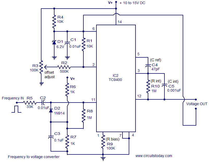
A very simple and low cost frequency to voltage converter based on the TC9400 IC from Microchip is shown here. TC9400 can be either wired as a voltage to frequency converter or frequency to voltage converter and it requires minimum external components. The functional blocks inside the TC9400 includes integrator opamp, 3uS delay circuit, one shot circuit, charge discharge control circuit, divide by 2 network and necessary drivers. This circuit finds application in a range of electronic projects like frequency meters, tachometers, speedometers, FM demodulators etc.
Circuit diagram.
frequency voltage converter
TC9400 Voltage to Frequency converter (Single supply version)
In the circuit shown above the TC9400 is wired as a F to V converter that operates from a single supply. The circuit generates an output voltage that is proportional to the input frequency. The input frequency is applied to the pin11 (non inverting input of the internal comparator). In order to trip the comparator the amplitude of the input frequency must be greater than +/-200mV.Below this level the circuit will not work at any situation.
Whenever the input signal to the pin 11 of IC1 crosses zero to the negative direction the output of the internal comparator goes low. The 3uS delay circuit enables the Cref charge/discharge circuit after 3uS and this connects the Cref to the reference voltage and this charges the integrating capacitor Cint a specific amount of voltage. In the single supply operation the reference voltage is the potential difference between pin 2 and 7 of the TC9400. Each time the input frequency wave form crosses zero towards positive direction, the output of the internal comparator goes high and this disables the Cref charge/discharge circuit which creates a short circuit across the Cref leads. The voltage across the integrating capacitor Cint is retained because the only discharge path available is the 1M resistor Rint which is a too high and the voltage across Cint is the output voltage. Resistor Rbiasis used to set the bias current of the IC.
The potential divider network comprising of R6 and R7 makes sure that the input threshold tracks the supply voltage always. The clamp circuit using diode D2 prevents the input from going far negative in order to turn on the internal comparator. In simple words this section of the circuit can be generally termed as a level shifter.
The TC9400 manufacturers claim that it can accept a signal of any frequency at its input. In the practical side, for the proper working of this circuit the positive half of the input signal must have at least 5uS pulse width and for the negative half it must be greater than or equal to 5uS.
For calibration adjust the offset adjust trimpot to obtain 0V at the output with no input frequency applied. If you have a function generator, set frequency input to 10KHz and make adjustments in the value of Cref to get around 2.5 to 3 volts at the output. This calibration is meant for a maximum input frequency of 10KHz.
Notes.
  • The circuit can be assembled on a Perf board or PCB.
  • The circuit can be powered from anything between 10 to 15V DC.
  • R3 can be used for adjusting the offset voltage.
  • In the circuit the inverting input of the internal comparator is referenced to 6.2V by using D1. So the input signals amplitude must be between 4V and the supply voltage (V+).
  • The output voltage is also referenced to 6.2V in this circuit.
  • The output voltage and input frequency of the F to V converter is related using the equation V out = V ref x C ref x F in where V out is the output voltage and F in is the input frequency.
  • TC9400 and TL071  must be mounted on holders.

Read more: http://www.circuitstoday.com/category/conversion-circuits#ixzz1HituOrB1
Under Creative Commons License: Attribution

Speaker to microphone converter circuit and explanation


Description.
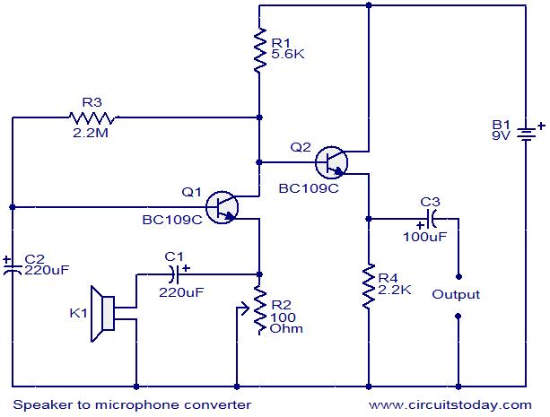
This circuit is a simple approach for converting a loud speaker into a microphone. When the sound waves fall on the diaphragm of a speaker, there will be fluctuations in the coil and there will be a small proportional induced voltage. Usually this induced voltage is very low in magnitude and useless. Here in the circuit the low voltage is amplified using transistors to produce a reasonable output. The transistor Q1 is wired in common base mode and produces the required voltage gain. The transistor Q2 is wired as an emitter follower to produce enough current gain. The voice quality of this circuit will not be as much as a conventional microphone but quite reasonable quality can be obtained. To set up the circuit, keep the preset R2 at around 10 Ohms and connect the battery. Now adjust R2 to obtain the optimum sound quality.
Circuit diagram with Parts list.
speaker-to-microphone-converter-circuit

Notes.
  • Assemble the circuit on a general purpose PCB.
  • Power the circuit from a 9 V PP3 battery.
  • A 3 inch speaker can be used as K1.
  • All capacitors must be rated at least 15V.
  • An 8 Ohm speaker or head phone can be connected at the output to hear the picked sound.

Read more: http://www.circuitstoday.com/category/conversion-circuits#ixzz1Hiur3FvU
Under Creative Commons License: Attribution

LM331 Frequency to voltage converter circuit and explanation


Description.
LM331 is basically a precision voltage to frequency converter from National Semiconductors. The IC has a hand full of applications like analog to digital conversion, long term integration, voltage to frequency conversion, frequency to voltage conversion. Wide dynamic range and excellent linearity makes the IC well suitable for the applications mentioned above.
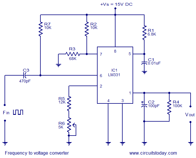
Here the LM331 is wired as a frequency to voltage converter which converts the input frequency into a proportional voltage which is extremely linear to the input frequency. The frequency to voltage conversion is attained by differentiating the input frequency using capacitor C3 and resistor R7 and feeding the resultant pulse train to the pin6 (threshold) of the IC. The negative going edge of the resultant pulse train at pin6 makes the built-in comparator circuit to trigger the timer circuit. At any instant, the current flowing out of the current output pin (pin 6) will be proportional to the input frequency and value of the timing components (R1 and C1). As a result a voltage (Vout) proportional to the input frequency (Fin) will be available across the load resistor R4.
Circuit diagram.
frequency to voltage converter using LM331
Notes.
  • The circuit can be assembled on a vero board.
  • I used 15V DC as the supply voltage (+Vs) while testing the circuit.
  • The LM331 can be operated from anything between 5 to 30V DC.
  • The value of R3 depends on the supply voltage and the equation is R3= (Vs – 2V)/ (2mA).
  • According to the equation, for Vs = 15V, R3=68K.
  • The output voltage depends on the equation, Vout = ((R4)/(R5+R6))*R1C1*2.09V*Fin.
  • POT R6 can be used for calibrating the circuit.

Read more: http://www.circuitstoday.com/category/conversion-circuits#ixzz1HiuekzyZ
Under Creative Commons License: Attribution

Simple AM Radio Receiver circuit and explanation


This circuit is essentially an amplified crystal set. The inductor could be a standard AM radio ferrite rod antenna while the tuning capacitor is a variable plastic dielectric gang, intended for small AM radios. The aerial tuned circuit feeds diode D1 which functions as the detector. A germanium type is far preferable to a silicon signal diode because its lower forward voltage enables it to work with smaller signals. The detected signal from the diode is filtered to remove RF and the recovered audio is fed to a 2-transistor stage which drives a set of 32O phones from a Walkman-style player.

Circuit diagram:
Simple AM radio receiver circuit schematic
Simple AM Radio Receiver Circuit Diagram
Author: Peter Goodwin
Copyright: Silicon Chip Electronics

Radio Controlled Electronic Flash circuit and explanation


A radio controlled electronic flash is a useful item in any photographer's kit. Professionals use them all the time. For example, a wedding photographer would put one behind the bride to back-light her gown and veil. You don't want wires showing in a shot like that. To build this control you will need an old R/C car (the simplest sort) in which the car runs in reverse at switch-on and goes ahead only when the remote is operated. They can be picked up cheaply as school fetes and garage sales. A typical car will run from 3V (two cells) and use 9V in the transmitter.

Before proceeding, make sure that the electronics in the car are operating. It doesn't matter if the wheels are broken or the motor is dead. You need to gain access to the leads to the motor. Normally (ie, without the remote operating), one is positive with respect to the other. Label them accordingly. On pressing the remote button, the polarity of the motor leads should swap. You will also need a flash extension cord you can cut into two sections. At the transmitter, the camera end of the extension cord is fed into the case and soldered to the control button contacts, as shown in Fig.1.

Circuit diagram:
Radio controlled electronic flash circuit schematic
Radio Controlled Electronic Flash Circuit Diagram

The contacts are in series with the battery supply, so if you don't want to open the transmitter, just cut one of the battery leads and connect the flash extension cord into the gap so created. You will then need to tape down the remote button so that it is permanently operated (ie, closed). All that needs to be done at the receiver end is to connect the normally negative motor lead to the gate circuit of an SCR, as shown in Fig.2, while the normally positive lead goes to the cathode of the SCR. Now, when the transmitter is operated by the camera's contacts, the lead polarity is reversed and the SCR acts as a switch to fire a portable electronic flash via the other half of the flash extension cord.

The transmitter can be attached to the camera via a flash bracket or a screw into the tripod socket, depending on what is the most convenient arrangement. The added components in the receiver can be mounted on Veroboard and housed in the space where the electric motor was. If appearance is a primary consideration, the receiver and the added components could be mounted in a standard jiffy box.

Finally, a note of caution:

When connecting the flash end half of the extension cord to the SCR, make sure that it is the positive wire which goes to the anode of the SCR. Flash cords do not always have the centre wire connected to the centre pin of the plug. The centre pin of the lead on the flash unit will be positive and this must connect to the anode of the SCR via the lead connected to the R/C receiver.
Author: A. J. Lowe - Copyright: Silicon Chip Electronics

455kHz IF Receivers DRM Down-Converter


This project came about due to my interest in a new form of radio transmission called DRM, which stands for "Digital Radio Mondiale" (see www.drm.org). This is a new form of digital shortwave transmission. A few devices are available from Europe for decoding the digital signals but are expensive. I decided instead to modify an existing circuit, using a stable purpose-built 470kHz ceramic resonator as the oscillator, rather than the original unstable L/C version. The 455kHz IF signal from a shortwave receiver is fed into the input (pin 1) of a double-balanced mixer and oscillator (IC1) via a level adjustment pot (VR1). The NE506’s output (pin 4) is then AC-coupled to a PC’s sound card input for processing. With the capacitor between pins 5 & 7 set to 150pF, the oscillator frequency should be around 467.5kHz. You can check if the oscillator is working by putting it near a receiver tuned to 467kHz. You should hear a beat frequency.

Circuit diagram:DRM down-converter for 455kHz IF receivers
DRM DownConverter Circuit Diagram For 455kHz IF Receivers

The IF signal of 455kHz is mixed with 467kHz, giving an output with a centre frequency of 12kHz. Sound cards should have no trouble sampling the 10kHz-wide DRM signal. A number of software-defined radio applications were found to work well with this converter. These applications perform all of the demodulation (SSB, AM, FM, etc) and various other DSP functions. If all is well, connect your 455kHz IF to the input and your computer sound card to the output. Run the Dream software (see http://drm.sourceforge.net), and tune to 6095Khz (RNZI), or 1440Khz (SBS). You should see the Dream software lock onto the DRM transmission and audio should start playing from the computer speakers. The NE602AN mixer/oscillator and 470kHz resonator are available for a cost of $12.50 - email the author for more details at jwtitmus@bigpond.com. A CD with various software defined receivers as well as the latest Dream software decoder is also available.
Author: John Titmuss
Copyright: Silicon Chip Electronics

Antenna Input & Audio Lineout Adaptor For Portable Radios


Here is an idea for a simple low-cost adaptor that allows a portable FM radio (or MP3 player with FM tuner) to be connected to an external antenna and to audio equipment such as a hifi system or PC sound card. Portable FM radios and some MP3 players typically provide a 3.5mm stereo jack socket for the headphone connection, with the shield conductor of the headphone cable doubling as an antenna.

The problem:

Recently, the author bought a cheap FM radio with a USB connector, designed to be operated with a PC. The package included an audio cable with a 3.5mm stereo phone plug at each end. The plug that goes into the radio has an additional wire (about 2m long) hanging out of it, which is meant to serve as an indoor antenna. When using the supplied cable, the system suffered from poor radio reception (too much interference), and poor audio quality (lack of bass). The first problem was easily explained, as the radio was used in a marginal TV/FM reception area. When the cable was "buzzed out", the reason for the second problem became apparent.

There was no audio ground connection, as the cable screen is not connected to anything at the radio end! As mentioned, the antenna wire in these units is connected to the "common" terminal of the 3.5mm socket, which normally doubles as the audio signal return path. If this terminal were to be connected to the ground of external audio equipment, the antenna signal would be clobbered. Perhaps the designer of this cable assumed that an adequate audio ground connection would be made indirectly via the USB cable – a poor assumption!

Circuit diagram:
Antenna input & audio lineout adaptor for portable radios circuit schematic
The challenge:

The challenge then was to provide a good antenna signal for the radio while at the same time making a good audio ground connection to external equipment. Preferably, this was to be achieved without relying on the USB connector (because not all FM radios have one) and without having to mess with the radio’s internal works. The accompanying circuit diagram shows how this can be achieved. The radio-frequency choke (L1) has a low impedance at audio frequencies, thereby making an audio ground path to the line output sockets from the radio’s antenna input ("common" terminal).

Conversely, the RFC presents a high impedance to the RF antenna signal, so preventing it from being shorted to ground. The antenna signal is coupled to the radio via two 220pF polystyrene (or ceramic) capacitors, which also block low-frequency interference (eg, mains hum). Note that the design relies on the capacitance in the audio cable to couple the antenna "ground" (cable shield) to the radio’s internal "ground".

Building it:

To build the adaptor, simply mount the parts in a small plastic box and wire up as shown. A suitable choke is available from Jaycar (Cat. No. LF-1534). The leads going to the 3.5mm plug should be no longer than about 100mm and need not be shielded. With a good TV/FM antenna, the author’s unit performed remarkably well, even in a poor FM reception area. The audio frequency response and signal-to-noise ratio were surprisingly good considering the low cost of the radio (about $40).
Author: Michael Bauer - Copyright: Silicon Chip Electronics

FM Transmitter Low Power circuit and explanation


This article should satisfy those who might want to build a low power FM transmitter. It is designed to use an input from another sound source (such as a guitar or microphone), and transmits on the commercial FM band - it is actually quite powerful, so make sure that you don't use it to transmit anything sensitive - it could easily be picked up from several hundred metres away. The FM band is 88 to 108MHz, and although it is getting fairly crowded nearly everywhere, you should still be able to find a blank spot on the dial.

NOTE: A few people have had trouble with this circuit. The biggest problem is not knowing if it is even oscillating, since the frequency is outside the range of most simple oscilloscopes. See Project 74 for a simple RF probe that will (or should) tell you that you have a useful signal at the antenna. If so, then you know it oscillates, and just have to find out at what frequency. This may require the use of an RF frequency counter if you just cannot locate the FM band.

Description

The circuit of the transmitter is shown in Figure 1, and as you can see it is quite simple. The first stage is the oscillator, and is tuned with the variable capacitor. Select an unused frequency, and carefully adjust C3 until the background noise stops (you have to disable the FM receiver's mute circuit to hear this).

Low Power FM TransmitterFigure 1 - Low Power FM Transmitter

Because the trimmer cap is very sensitive, make the final frequency adjustment on the receiver. When assembling the circuit, make sure the rotor of C3 is connected to the +9V supply. This ensures that there will be minimal frequency disturbance when the screwdriver touches the adjustment shaft. You can use a small piece of non copper-clad circuit board to make a screwdriver - this will not alter the frequency.

The frequency stability is improved considerably by adding a capacitor from the base of Q1 to ground. This ensures that the transistor operates in true common base at RF. A value of 1nF (ceramic) as shown is suitable, and will also limit the HF response to 15 kHz - this is a benefit for a simple circuit like this, and even commercial FM is usually limited to a 15kHz bandwidth.

Capacitors
All capacitors must be ceramic (with the exception of C1, see below), with C2 and C6 preferably being N750 (Negative temperature coefficient, 750 parts per million per degree Celsius). The others should be NPO types, since temperature correction is not needed (nor is it desirable). If you cannot get N750 caps, don't worry too much, the frequency stability of the circuit is not that good anyway (as with all simple transmitters).

How It Works
Q1 is the oscillator, and is a conventional Colpitts design. L1 and C3 (in parallel with C2) tunes the circuit to the desired frequency, and the output (from the emitter of Q1) is fed to the buffer and amplifier Q2. This isolates the antenna from the oscillator giving much better frequency stability, as well as providing considerable extra gain. L2 and C6 form a tuned collector load, and C7 helps to further isolate the circuit from the antenna, as well as preventing any possibility of short circuits should the antenna contact the grounded metal case that would normally be used for the complete transmitter.

The audio signal applied to the base of Q1 causes the frequency to change, as the transistor's collector current is modulated by the audio. This provides the frequency modulation (FM) that can be received on any standard FM band receiver. The audio input must be kept to a maximum of about 100mV, although this will vary somewhat from one unit to the next. Higher levels will cause the deviation (the maximum frequency shift) to exceed the limits in the receiver - usually ±75kHz.

With the value shown for C1, this limits the lower frequency response to about 50Hz (based only on R1, which is somewhat pessimistic) - if you need to go lower than this, then use a 1uF cap instead, which will allow a response down to at least 15Hz. C1 may be polyester or mylar, or a 1uF electrolytic may be used, either bipolar or polarised. If polarised, the positive terminal must connect to the 10k resistor.

Inductors
The inductors are nominally 10 turns (actually 9.5) of 1mm diameter enamelled copper wire. They are close wound on a 3mm diameter former, which is removed after the coils are wound. Carefully scrape away the enamel where the coil ends will go through the board - all the enamel must be removed to ensure good contact. Figure 2 shows a detail drawing of a coil. The coils should be mounted about 2mm above the board.

For those still stuck in the dark ages with imperial measurements (grin), 1mm is about 0.04" (0.0394") or 5/127 inch (chuckle) - you will have to work out what gauge that is, depending on which wire gauge system you use (there are several). You can see the benefits of metric already, can't you? To work out the other measurements, 1" = 25.4mm

NOTE: The inductors are critical, and must be wound exactly as described, or the frequency will be wrong.

Figure 2 - Detail Of L1 And L2

The nominal (and very approximate) inductance for the coils is about 130nH.This is calculated according to the formula ...

L = N² * r² / (228r + 254l)

... where L = inductance in microhenries (uH), N = number of turns, r = average coil radius (2.0mm for the coil as shown), and l = coil length. All dimensions are in millimetres.

Pre-Emphasis

It is normal with FM transmission that "pre-emphasis" is used, and there is a corresponding amount of de-emphasis at the receiver. There are two standards (of course) - most of the world uses a 50us time constant, and the US uses 75us. These time constants represent a frequency of 3183Hz and 2122Hz respectively. This is the 3dB point of a simple filter that boosts the high frequencies on transmission and cuts the same highs again on reception, restoring the frequency response to normal, and reducing noise.

The simple transmitter above does not have this built in, so it can be added to the microphone preamp or line stage buffer circuit. These are both shown in Figure 3, and are of much higher quality than the standard offerings in most other designs.

Low Power FM TransmitterFigure 3 - Mic And Line Preamps

Rather than a simple single transistor amp, using a TL061 opamp gives much better distortion figures, and a more predictable output impedance to the transmitter. If you want to use a dynamic microphone, leave out R1 (5.6k) since this is only needed to power an electret mic insert. The gain control (for either circuit) can be an internal preset, or a normal pot to allow adjustment to the maximum level without distortion with different signal sources. The 100nF bypass capacitors must be ceramic types, because of the frequency. Note that although a TL072 might work, they are not designed to operate at the low supply voltage used. The TL061 is specifically designed for low power operation.

The mic preamp has a maximum gain of 22, giving a microphone sensitivity of around 5mV. The line preamp has a gain of unity, so maximum input sensitivity is 100mV. Select the appropriate capacitor value for pre-emphasis as shown in Figure 3 depending on where you live. The pre-emphasis is not especially accurate, but will be quite good enough for the sorts of uses that a low power FM transmitter will be put to. Needless to say, this does not include "bugging" of rooms, as this is illegal almost everywhere.

I would advise that the preamp be in its own small sub-enclosure to prevent RF from entering the opamp input. This does not need to be anything fancy, and you could even just wrap some insulation around the preamp then just wrap the entire preamp unit in aluminium foil. Remember to make a good earth connection to the foil, or the shielding will serve no purpose.
source: http://sound.westhost.com/project54.htm

Smart Trailing Socket circuit and explanation


Mains sockets switched automatically by a Control Socket, Up to 1000W switched power

This circuit consists of a Trailing Socket (also called Extension or Distribution Socket) or similar device where two, three or more sockets (depending on the box dimensions and on constructor's needs) will be powered only when a current flows in the Control Socket. For example: if an electric drill is connected to the Control Socket, the Switched Sockets will be powered each time the electric drill is running. In this case, a lamp could be connected to a Switched Socket and will illuminate when the drill is operating.

Another example: a desk lamp could be connected to the Control Socket and a PC, a Monitor and a Printer could be connected to the Switched Sockets and will be running after the lamp is switched on. Switching off the lamp, all the above mentioned appliances will be automatically switched off. A further application is the control of a High Fidelity chain, plugging the Power Amplifier in the Control Socket and - for example - CD Player, Tape Recorder, and Tuner in the Switched Sockets.

Usually, trailing sockets are placed to the rear of the appliances, often in places not easily reachable, so, even if the socket has a switch, it is much easier to switch on and off the High Fidelity chain from the main amplifier itself. The same consideration is valid for computer-monitor-printer chains etc. Nevertheless, in this case, the use of a table lamp plugged in the Control Socket is almost mandatory, as explained below. In fact, this very sensitive circuit works fine when appliances having full breaking switches like lamps, drills, most power amplifiers, old radios, old TV sets, fans, almost all electrical household appliances etc. are plugged in the Control Socket.

This is because these devices have a switch that fully excludes the internal circuitry from the mains. Unfortunately, in modern devices like computers, monitors, CD players, recent radios and TV sets (usually powered by means of internal "switching" supplies), the power switch does not completely isolate the internal circuitry from the mains, as transient suppressors and other components remain on circuit. This causes a very small current to flow across the sensing circuitry, but sufficient to trigger the output Triac.

Therefore, the switched devices will remain always on, no matter if the control appliance is on or off. This could also happen when devices connected to the mains by means of plug-in power supply adapters are used as control appliances, due to their lack of a mains switch. In spite of this restriction, the circuit can be still useful, due to the high number and variety of devices allowing impeccable performance when they are plugged in the Control Socket.

Circuit diagram:
smart trailing socket circuit schematic
Smart Trailing Socket Circuit Diagram
Parts:

R1,R2_________100R 1/2W Resistors
C1____________100nF 630V Polyester Capacitor
D1 to D6_____1N5408 1000V 3A Diodes (See Notes)
D7__________TIC225M 600V 8A Sensitive Gate Triac (See Notes)
A commercial trailing socket to be modified or a self-made box with several sockets.

Circuit operation:

Six back-to-back power diodes are connected in series to the Control Socket. The current drawn by the device plugged into this socket when in the on state, flowing through the diode chain, causes a voltage drop of about 2V. This voltage, limited by R1, drives the Gate of the Triac D7 which, in turn, will switch the output sockets. C1 and R2 form a so called "Snubber network", helping to eliminate switching transients generated by inductive loads.

Notes:
  • The circuit is sufficiently small to be embedded into some types of commercial trailing sockets, or a box with a number of sockets can be made at will.
  • The diode types suggested in the Parts List for D1 to D6 will allow an appliance of up to about 500W power to be plugged in the Control Socket. Use BY550-800 diodes for up to 800 - 1000W.
  • For less demanding appliances, 1N4007 diodes will allow up to 200W power.
  • The Triac type suggested in the Parts List for D7 will allow a total power available to the Switched Sockets of more than 1000W. If you intend to drive loads of more than 500W total, please use a suitable heatsink.
  • Wanting to drive less powerful loads, you can use for D7 a TIC216M (up to 800 - 1000W) or a TIC206M (up to 500 - 600W).
  • Warning! The device is connected to 230Vac mains, so some parts in the circuit board are subjected to lethal potential! Avoid touching the circuit when the mains cord is plugged in!
Copyright: www.redcircuits.com
If you want to report any meterial please